Home
Texas Instruments
Computer Accessories
Metawatch MSP-WDS Series
Page 34 (MSP-FET430 UIF USB Interface, Schematic (4 of 4))
Texas Instruments Metawatch MSP-WDS Series - MSP-FET430 UIF USB Interface, Schematic (4 of 4)
51 pages
Manual
To Next Page
To Next Page
To Previous Page
To Previous Page
Loading...
Debug
Probes
Hardware
and
Software
www.ti.com
34
SLAU647F
–
July
2015
–
Revised
December
2016
Submit
Documentation
Feedback
Copyright
©
2015–2016,
Texas
Instruments
Incorporated
MSP
Debuggers
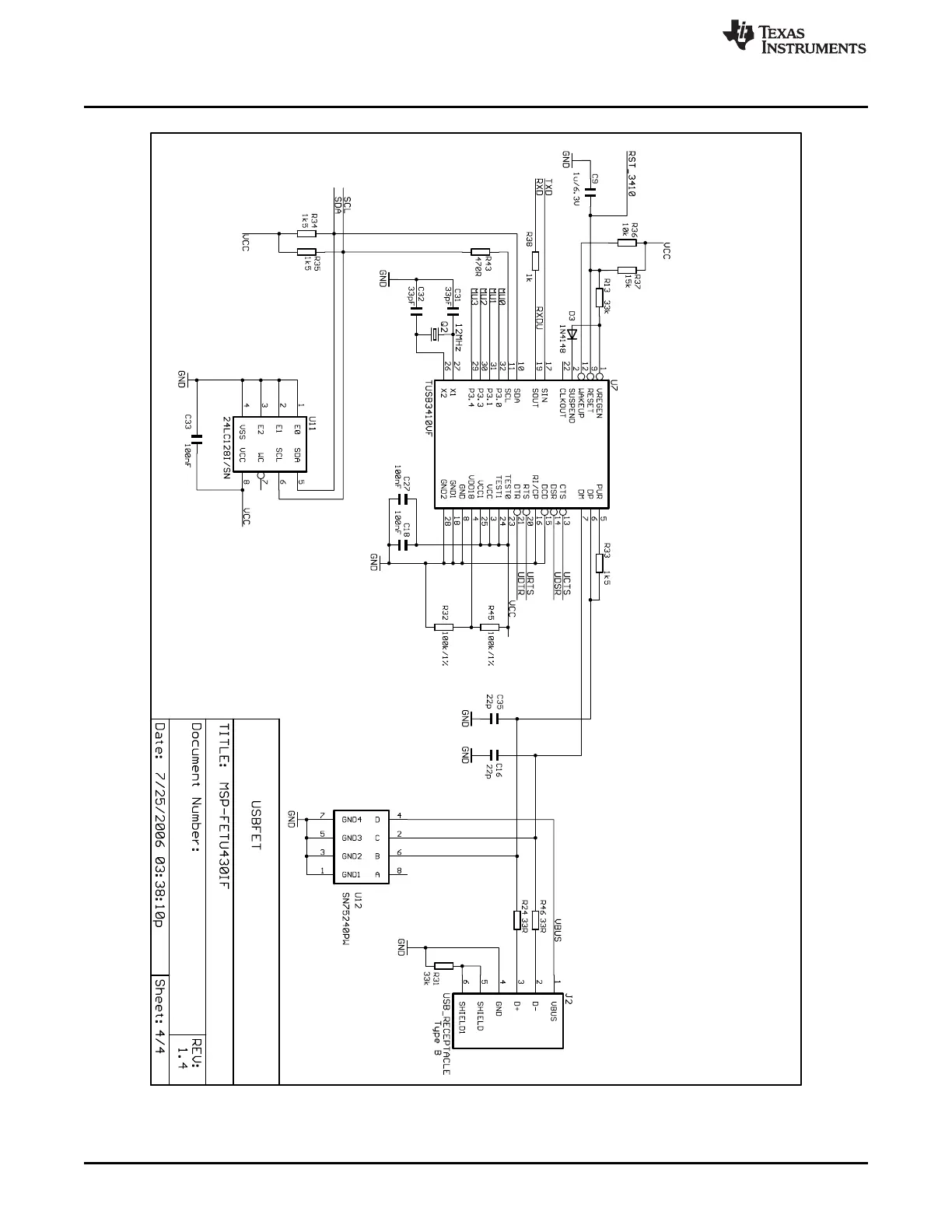
Figure
29.
MSP-FET430UIF
USB
Interface,
Schematic
(4
of
4)
33
35
Table of Contents
Main Page
Table of Contents
1
Introduction
3
MSP Debug Probe Overview
4
Hardware Identification
6
Ez-FET Emulation IP
6
Ez-FET Lite Emulation IP
6
List of Figures 1 Ez-FET Windows Enumeration
6
Ez430 Emulation IP
7
Ez430 Windows Enumeration
7
Hardware Installation
8
MSP Flasher Driver Install Notification
10
CCS Cloud Agent Installation
11
Successful CCS Cloud Agent Installation
11
Debug Probes Hardware and Software
12
MSP Ecosystem
12
MSP-FET Top View
15
MSP-FET Bottom View
15
MSP-FET 14-Pin JTAG Connector
18
Open MSP-FET Cover
20
Jumper J5
20
Recovery Confirmation
21
MSP-FET USB Debugger, Schematic (1 of 5)
22
MSP-FET USB Debugger, Schematic (2 of 5)
23
MSP-FET USB Debugger, Schematic (3 of 5)
24
MSP-FET USB Debugger, Schematic (4 of 5)
25
MSP-FET USB Debugger, Schematic (5 of 5)
26
MSP-FET USB Debugger, PCB (Top)
26
MSP-FET USB Debugger, PCB (Bottom)
26
MSP-FET430UIF Version 1.4A Top and Bottom Views
28
MSP-FET430UIF Version 1.3 Top and Bottom Views
28
MSP-FET430UIF 14-Pin JTAG Connector
29
MSP-FET430UIF USB Interface, Schematic (1 of 4)
31
MSP-FET430UIF USB Interface, Schematic (2 of 4)
32
MSP-FET430UIF USB Interface, Schematic (3 of 4)
33
MSP-FET430UIF USB Interface, Schematic (4 of 4)
34
Related product manuals
Texas Instruments MSP Series
80 pages
Texas Instruments MSP-FET430X110
80 pages
Texas Instruments XDS110
28 pages
 Loading...