www.ti.com
Debug Probes Hardware and Software
19
SLAU647F–July 2015–Revised December 2016
Submit Documentation Feedback
Copyright © 2015–2016, Texas Instruments Incorporated
MSP Debuggers
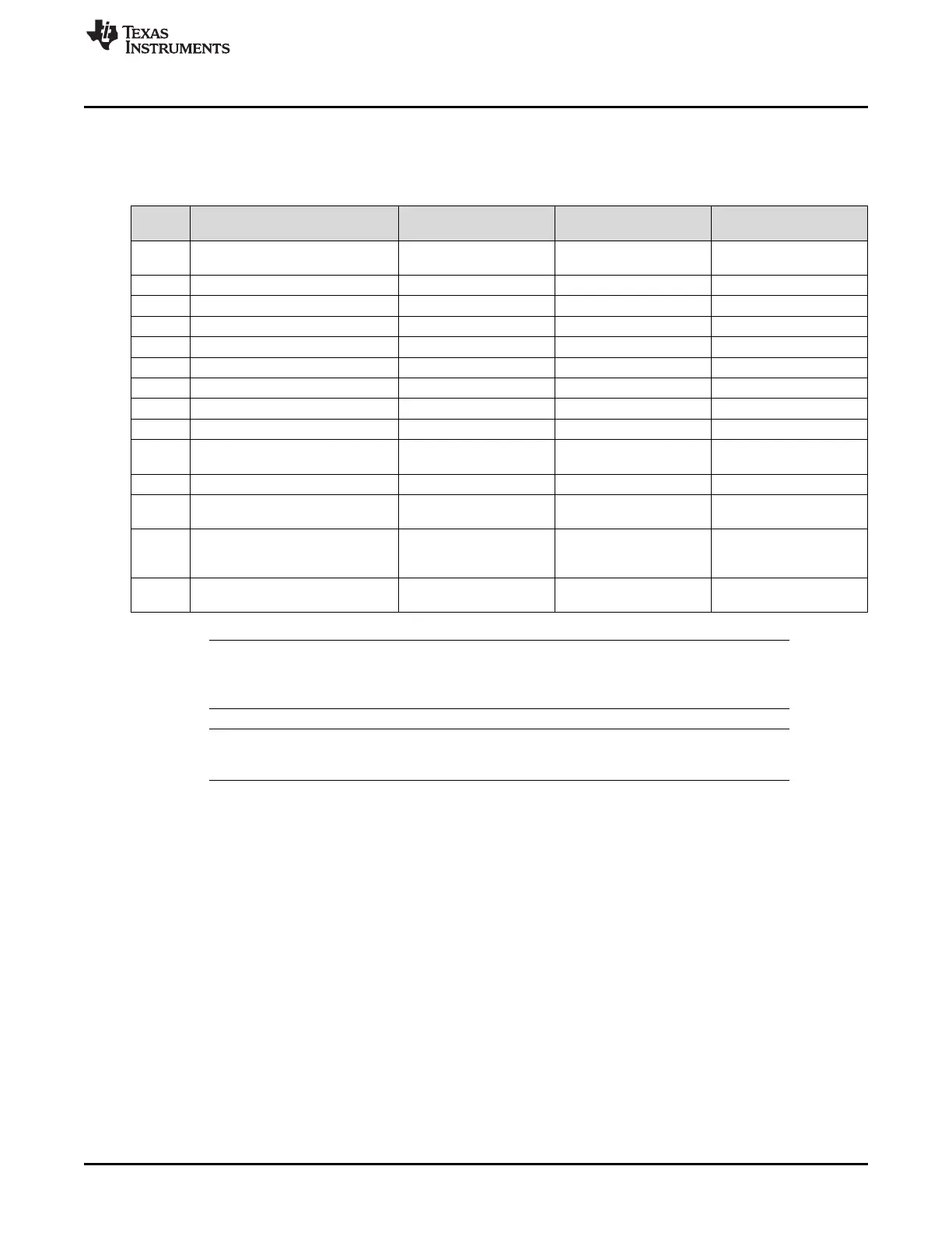
5.6.5.2 MSP-FET Pin States After Power Up
Table 6 describes the electrical state of every JTAG pin after debug probe power up.
Table 6. MSP-FET Pin States
Pin Name After Power up
When JTAG Protocol is
Active
When Spy-Bi-Wire
Protocol is Active
1 TDO/TDI Hi-Z, pulled up to 3.3 V In, TDO
In and Out, SBWTDIO
(RST pin)
2 VCC_TOOL 3.3 V Target V
CC
Target V
CC
3 TDI/VPP Hi-Z, pulled up to 3.3 V Out, TDI Hi-Z, pulled up to V
CC
4 VCC_TARGET In, external V
CC
sense In, external V
CC
sense In, external V
CC
sense
5 TMS Hi-Z, pulled up to 3.3 V Out, TMS Hi-Z, pulled up to V
CC
6 N/C N/C N/C N/C
7 TCK Hi-Z, pulled up to 3.3 V Out, TCK Out, SBWTCK
8 TEST/VPP Out, Ground Out, TEST Hi-Z, pulled up to V
CC
9 GND Ground Ground Ground
10 UART_CTS/SPI_CLK/I2C_SCL Hi-Z, pulled up to 3.3 V
Out, Target UART Clear-
To-Send Handshake input
Out, Target UART Clear-
To-Send Handshake input
11 RST Out, V
CC
Out, RST Ground
12 UART_TXD/SPI_SOMI/I2C_SDA Hi-Z, pulled up to 3.3 V
In, Target UART TXD
output
In, Target UART TXD
output
13 UART_RTS Hi-Z, pulled up to 3.3 V
In, Target UART Ready-
to-Send Handshake
output
In, Target UART Ready-to
Send Handshake output
14 UART_RXD/SPI_SIMO Hi-Z, pulled up to 3.3 V
Out, Target UART RXD
input
Out, Target UART RXD
input
NOTE: To enable the UART, I
2
C or SPI pins, the correct invalid baud rate activation command must
be sent (see MSP-FET Backchannel UART Activation Commands and MSP-FET MSP
Target BSL Activation Commands). After this, the pins switch to the states in Table 6.
NOTE: MSP430BSL-SPI support is currently not available using the MSP-FET. The pin names used
in Table 6 are the same as the names that are printed on the back of the MSP-FET.
 Loading...