46 Chapter 2: TI-83 Plus Specific Information
TI-83 Plus Developer Guide Third Release May 28, 2002
PagedGet
This routine has two functions. First is to fill the 16 byte cache
with mode data from the archive, whenever it has been
completely read. Second, is to return the next byte from the
cache to the caller. The first byte returned is at the location
input to SetupPagedPtr, followed by each consecutive byte
that follows.
Inputs:
Initial inputs are set by SetupPagedPtr, and are updated after
each subsequent call to PagedGet.
Outputs: ACC = byte read.
Cache pointers updated.
Cache reloaded with next 16 bytes of archive if exhausted.
Note: Both of these methods, direct and cached, will force an application to read data
from the archive sequentially. This can be very inefficient if the eightieth byte of an
archived equation needed to be read. An application would have to read through the
first 79 bytes one at a time.
In Ram, the solution would be to add 80 to the address of the start of the equation
and then do one read. In the archive, it is not as simple. An application has to be
wary of ROM page boundaries and offsets into a ROM page.
Applications can use the following code to add a two byte value to a ROM page
and offset archive address, so that page boundary crossing is adjusted for. This
routine will work for adding values up to 4000h (16K) maximum.
;
; Add DE to ROM page and offset: B, HL
;
BHL_Plus_DE:
ADD HL,DE ; add DE to the offset HL
BIT 7,H ; cross page boundary?
RET Z ; no, B, HL = ROM page and offset
;
INC B ; increase ROM page number
RES 7,H
SET 6,H ; adjust offset to be in 4000h
; to 7FFFh
RET
For example, look up archived AppVar MYAPPVAR, and read past its Symbol
Table entry in the archive to reach the data. Then read the two size bytes of the
AppVar.
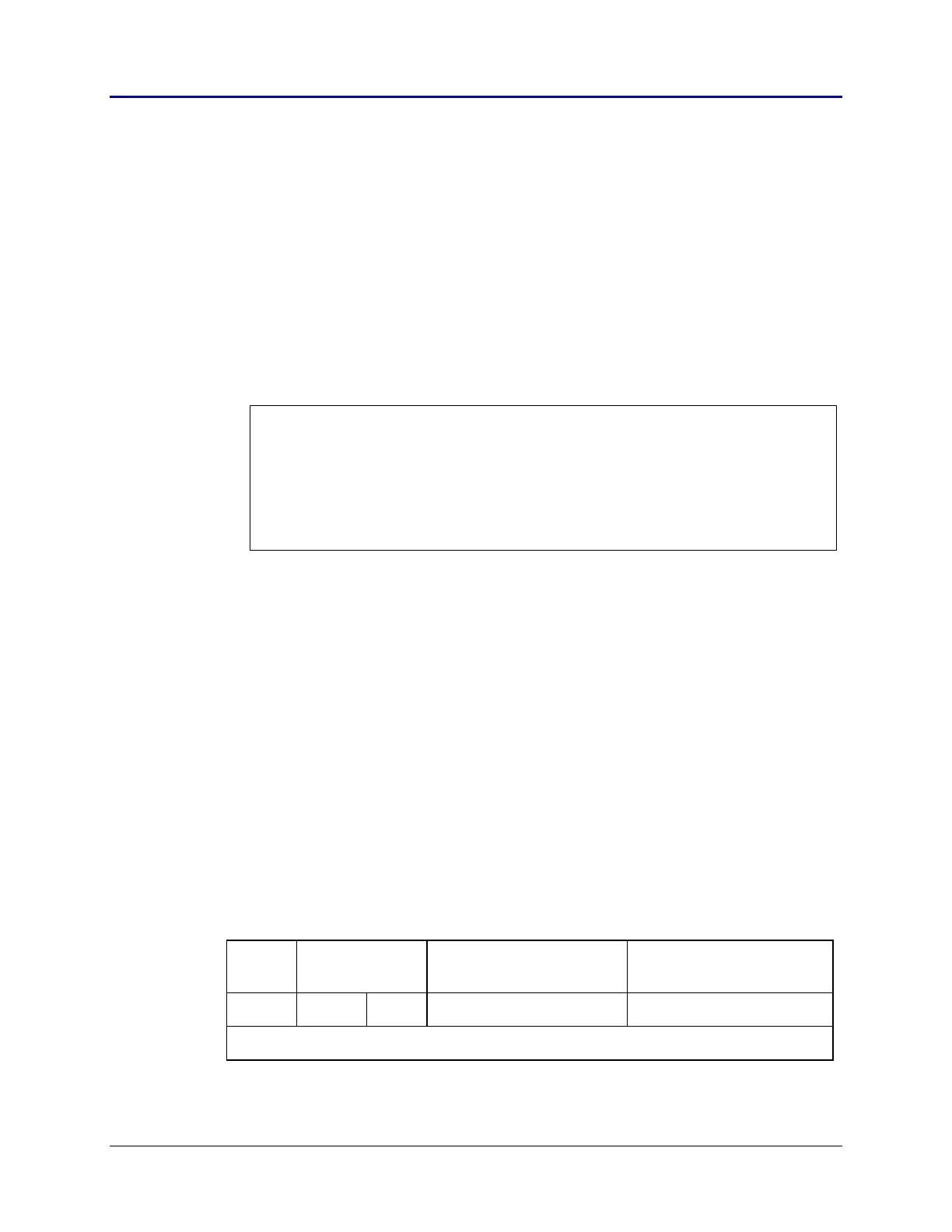
Data
valid
Size of Symbol
entry + Data
Size varies by the name
size and data type
Size computed the same
as variables in RAM
Flag LSB MSB Symbol Table entry Variable Data Structure
Increasing addresses -------->
Table 2.12: Format of Archive Stored Variables