76 Chapter 2: TI-83 Plus Specific Information
TI-83 Plus Developer Guide Third Release May 28, 2002
Modifying Display Format Settings
Resetting the next two flags signifies NORMAL mode setting.
fmtExponent, (fmtFlags) = 1 for scientific display mode
fmtEng, (IY + fmtFlags) = 1 for engineering display mode
fmtRect, (IY + numMode) = 1 rectangular complex display mode
fmtPolar, (IY + numMode) = 1 polar complex display mode
Fix setting:
(fmtDigits) = 0FFh for FLOAT, no fix setting
= 0 – 9 if a fix setting is specified
Writing Directly to the Display Driver
The display driver is a device that controls the display. The driver contains RAM that
represents what is currently being displayed. Commands are sent to the driver to
modify, or access what is displayed. The following is a brief description of the
commands that control the driver which is the Toshiba T6A04.
• Driver RAM
The RAM on the driver is mapped to a grid of 64 rows of 12 bytes. Each row
represents a row of pixels in the display with each byte representing eight pixels.
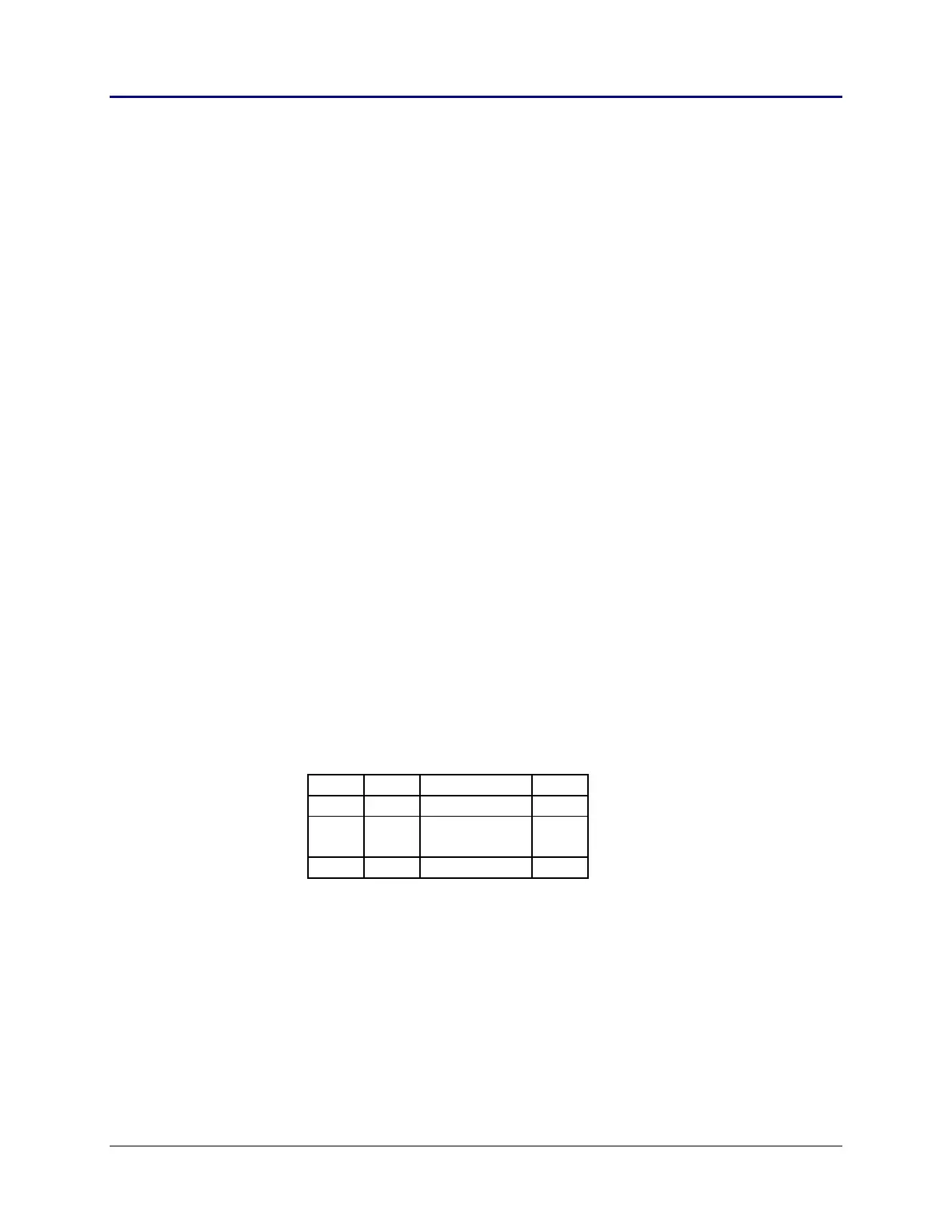
The addressing of the RAM is done by setting a row and column value to address a
particular byte. The addressing is built into the command used to set either a row or
column value. The figure below shows the command values used to set either a row
(X) or column (Y) value.
20h 21h Y Direction 2Bh
80h
81h
X
Direction
BFh
Fig. 2.11: Command Values
The first byte — row 80h and column 20h — represents the eight pixels in the first
row of the display’s left edge. The most significant bit of the byte is the left most
pixel.
• Sending Commands
The following areas must be considered when sending commands.
– Interrupts should be disabled to send commands/data to the driver.