86 Chapter 2: TI-83 Plus Specific Information
TI-83 Plus Developer Guide Third Release May 28, 2002
012
92 93 94 95
63
62
61
.
.
.
2
1
0
Y Coordinate
...
...
...
...
.
.
.
...
…
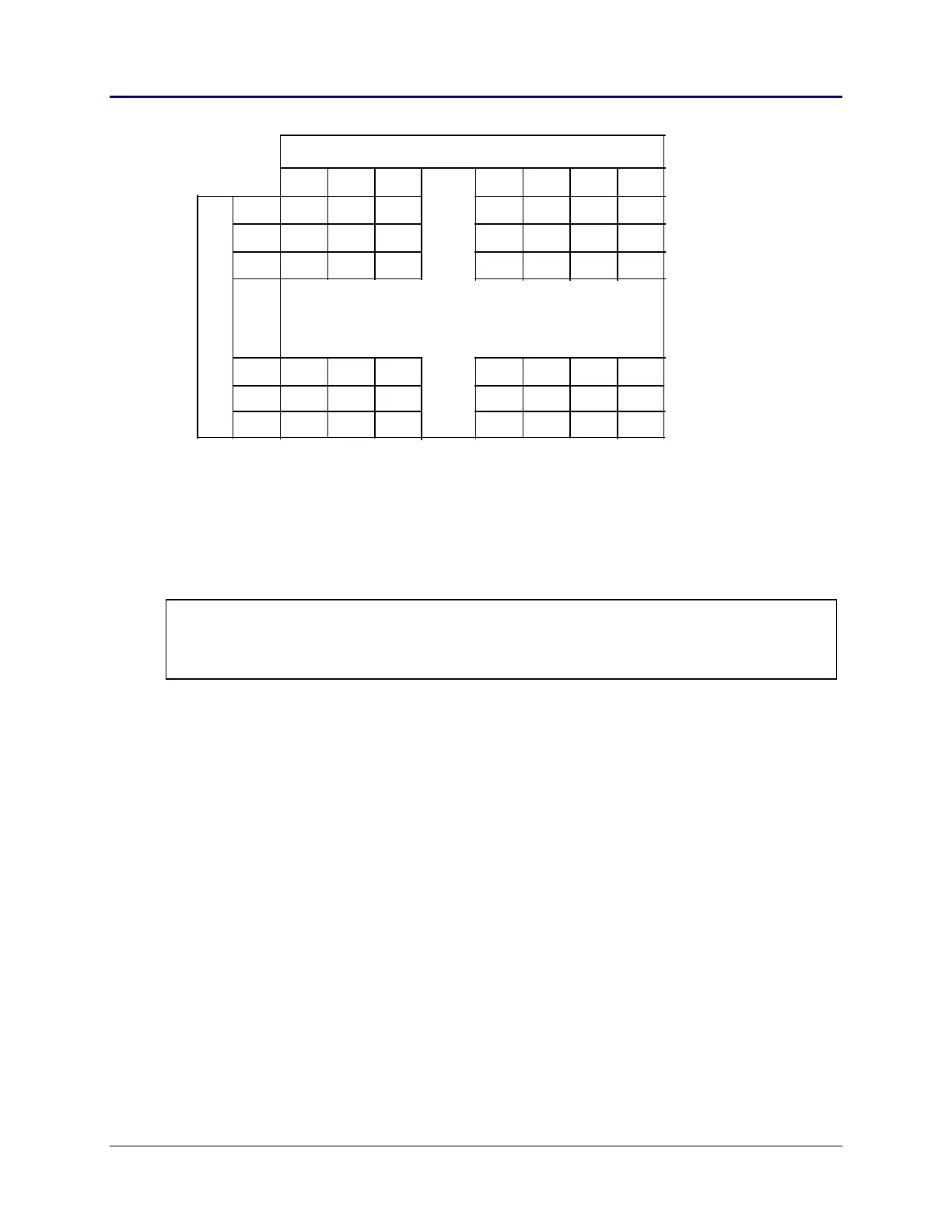
X Coordinate
Fig. 2.12: Pixel Coordinates
Coordinates are input to drawing routines mainly in a register pair such as BC, where
BC = (X,Y) drawing pixel coordinate.
For example, the upper top left pixel in the display is drawing pixel coordinates
(0,63); (X,Y).
Note: The drawing routines, by default, DO NOT use the last row of pixels, Y = 0 and the last column of
pixels, X = 95. This is done to allow for an odd number of pixels for both the X and Y axes. This
restriction can be overridden thus allowing for the drawing routines to make use of the entire
display.
• Drawing in a split screen
If either Horizontal or Vertical (G-T) split screen is the current mode, the output from
the drawing routines will be affected. Listed below are the effects of each split mode.
Horizontal
Valid Y pixel range = 1 – 31, where Y-pixel row 1 is moved up
32 rows from its normal position.
Vertical (G-T)
Valid Y pixel range = 1 – 51, where Y-pixel row 1 is moved up
12 rows from its normal position.
Valid X pixel range = 0 – 31, with X-pixel column 0 in its original
position.
If split screen modes are not required by an application, it is recommended that all
drawing routines be performed with no split modes set. See the Split Screen section
for further information.