Usage Notes and Known Design Exceptions to Functional Specifications
www.ti.com
6
SPRZ412K–December 2013–Revised February 2020
Submit Documentation Feedback
Copyright © 2013–2020, Texas Instruments Incorporated
TMS320F2837xD Dual-Core MCUs Silicon Revisions C, B, A, 0
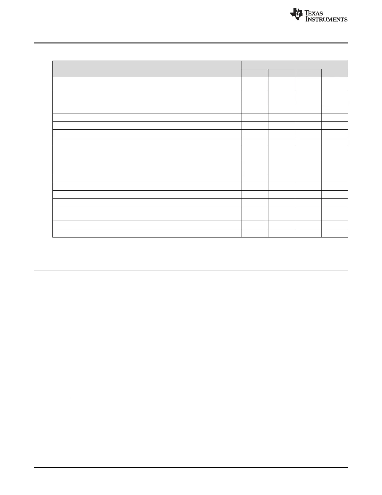
Table 3. List of Advisories (continued)
TITLE
SILICON REVISION(S) AFFECTED
0 A B C
ePWM: An ePWM Glitch can Occur if a Trip Remains Active at the End of the
Blanking Window
Yes Yes Yes Yes
ePWM: ePWM Dead-Band Delay Value Cannot be Set to 0 When Using Shadow
Load Mode for RED/FED
Yes Yes Yes Yes
SYSTEM: Multiple Successive Writes to CLKSRCCTL1 Can Cause a System Hang Yes Yes Yes Yes
CMPSS: COMPxLATCH May Not Clear Properly Under Certain Conditions Yes Yes Yes Yes
CMPSS: Ramp Generator May Not Start Under Certain Conditions Yes Yes Yes Yes
CMPSS: CMPIN4N, CMPIN4P, CMPIN5N, and CMPIN5P Not Available Yes Yes
GPIO: Open-Drain Configuration May Drive a Short High Pulse Yes Yes Yes Yes
GPIO: GPIO0–GPIO7, GPIO46, GPIO47 Shunt to V
SS
Due to Fast Transients at
High Temperature
Yes Yes
During DCAN FIFO Mode, Received Messages May be Placed Out of Order in the
FIFO Buffer
Yes Yes Yes Yes
Boot ROM: Calling SCI Bootloader from Application Yes Yes Yes Yes
Boot ROM: Using CPU1 Wait Boot or CPU2 Idle Mode Yes Yes Yes Yes
Boot ROM: Device Will Hang During Boot if X1 Clock Source is not Present Yes
HRPWM: HRCNFG Register Reads and Bit-Wise Writes Yes Yes
SYSBIOS in ROM References Different Flash Sector (Changed From Sector A to
Sector B)
Yes Yes
McBSP: McBSP Transmit in SPI Slave Mode Yes Yes
Crystal: Maximum Equivalent Series Resistance (ESR) Values are Reduced Yes Yes
Table 4. Table of Contents for Advisories
Title ...................................................................................................................................... Page
Advisory —Analog Bandgap References ............................................................................................. 8
Advisory —Analog Trim of Some TMX Devices ..................................................................................... 9
Advisory —ADC: ADC Post-Processing Block Limit Compare................................................................... 10
Advisory —ADC: Interrupts may Stop if INTxCONT (Continue-to-Interrupt Mode) is not Set ............................... 10
Advisory —ADC: ADC Offset Trim in Different Modes ............................................................................ 11
Advisory —ADC: DMA Read of Stale Result ....................................................................................... 11
Advisory —ADC: Random Conversion Errors ...................................................................................... 12
Advisory —ADC: ADC PPB Event Trigger (ADCxEVT) to ePWM Digital Compare Submodule ............................ 12
Advisory —ADC: 12-Bit Switch Resistance ........................................................................................ 12
Advisory —ADC: 12-Bit Input Capacitance When Switching Channel Groups ................................................ 13
Advisory —ADC: Functionality of V
REFLO
Pins....................................................................................... 13
Advisory —ADC: Sensitivity to ESD Events ....................................................................................... 13
Advisory —ADC: ADC Input Multiplexer Connection at Beginning of Acquisition Window................................... 14
Advisory —ADC: ADC Sparkle Codes............................................................................................... 15
Advisory —ADC: ADC Linearity Performance...................................................................................... 15
Advisory —XRS may Toggle During Power Up .................................................................................... 16
Advisory —USB: USB DMA Event Triggers are not Supported.................................................................. 16
Advisory —VREG: VREG Will be Enabled During Power Up Irrespective of VREGENZ .................................... 16
Advisory —Flash: A Single-Bit ECC Error May Cause Endless Calls to Single-Bit-Error ISR ............................... 17
Advisory —Flash: Minimum Programming Word Size............................................................................. 17
Advisory —Flash: Reset of CPU2 While it has Pump Ownership Can Cause Erroneous Flash Reads From CPU1..... 18
Advisory —ePIE: Spurious VCU Interrupt (ePIE 12.6) Can Occur When First Enabled...................................... 19
Advisory —eQEP: Position Counter Incorrectly Reset on Direction Change During Index .................................. 20

 Loading...


