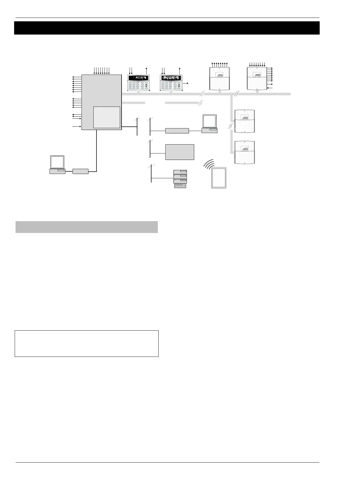
8 Programmable***
100mA Outputs
Bell Tamper Input
Auxiliary Tamper Input
5 Programmable Outputs
(4 x 500mA & 1 Relay)
( only)Premier 88 168, & 640
Premier Elite
48/ 88/12/24/ 64/
/640*168
Premier LCD/LCDP Premier LCDL/LCDLP
Premier Elite LCDLP/SMK/FMK
4 Wire Data Network 1
16 Programmable
100mA Outputs
2 keypads ( 12-W)Elite
4 keypads ( /W)Elite 24
4 Keypads ( /W & 64-W)Elite 48
8 Keypads ( )Elite 88
16 Keypads ( )Elite 168
64 Keypads ( ) Elite 640
Premier OP16******
1 Output Module ( )Elite 12**
1 Output Module ( )Elite 24
2 Output Modules ( & 64)Elite 48
4 Output Modules ( )Elite 88
8 Output Modules ( )Elite 168
32 Output Modules( ) Elite 640
8 Zone Inputs
Alarm Receiving
Centre
Modem
PC and Modem for
Remote Upload/Download
PC-Com
PC and forPC-Com
Local Upload/Download
Plug on Digimodem
(Com300, Com2400)
GSM Module
ComIP, ComWiFi*****
WebwayOne, Emizon
or Chiron Iris
2 Zone
Inputs
1Programmable
100mA Output
2 Zone
Inputs
1Programmable
100mA Output
Speaker
Output
Additional
4 Wire Data Network
Speaker Output
8 Zone Inputs
Auxiliary Input
Premier 8XP****
8 Programmable
100mA Outputs
0 Expanders ( )Elite 12
2 Expanders ( )Elite 24
4 Expanders ( & 64)Elite 48
8 Expanders ( )Elite 88
16 Expanders ( )Elite 168
64 Expanders ( )Elite 640
Wire as Network 1
4 to 16 Zones ( 12-W)Elite
8/4 to 24 zones ( /W)Elite 24
8/4 to 48 Zones ( /W)Elite 48
4 to 76 Zones ( 64-W)Elite
8 to 88 Zones ( )Elite 88
8 to 168 Zones ( )Elite 168
0 to 640 Zones ( ) Elite 640
Power
Info.
Ready
ServiceOmi
Power
Info.
Ready
ServiceOmit
Bell/Strobe Outputs
Area
Yes
Part
Chime
Omit Rese t
Menu
2 abc
No
1 3 def
6 mno
9 wxyz
5 jkl
8 tuv
0
4 ghi
7 pqrs
Area
Yes
Part
Chime
Omit Rese t
Menu
2 abc
No
1 3 def
6 mno
9 wxyz
5 jkl
8 tuv
0
4 ghi
7 pqrs
Premier
Power
Network No
Address
Zones
Power
Network No
Addre ss
Zone s
* No Onboard Zones
** 8 Only on Elite 12
*** 3 Only on Elite 12
**** When mixing wired and wireless expanders check total zone capacity for the control panel.
*****ComWiFi should not be used as a primary form of signalling to an ARC
****** Cannot be used at the same address as Wireless expanders
Premier 8XPElite -W****
Power
Network No
Address
Zones
0 Expanders ( )Elite 12
2 Expanders ( )Elite 24
4 Expanders ( )Elite 48
8 Expanders ( )Elite 64 & 88
16 Expanders ( )Elite 168
64 Expanders ( )Elite 640
Premier XP Elite 32 -W****
Power
Network No
Address
Zones
0 Expanders ( )Elite 12
1 Expanders ( )Elite 24
1 Expanders ( )Elite 48
2 Expanders ( )Elite 64 & 88
4 Expanders ( )Elite 168
16 Expanders ( )Elite 640
Mobile APP Server
Push Notifications/Arm/Disram
iOS
or
Android
Device
Installation Sequence
Before attempting to install the alarm system, read this section.
Once you have an overall understanding of the installation
sequence, carefully work through each step.
1: Design the Layout
Make a rough sketch of the premises to get an idea of where the
alarm detection devices, keypads, zone expanders etc. are to be
located.
2: Mounting the Panel
The control panel should be mounted in a dry area close to an
unswitched AC power source and the incoming telephone line (if
using a communicator). Mount the control panel on a flat, plumb
wall using at least three screws of appropriate size.
You must complete all wiring before connecting the battery or applying
AC mains to the control panel.
WARNING: ELECTRICITY CAN KILL
BEFORE connecting the control panel ALWAYS
disconnect the supply at the consumer unit.If in ANY
doubt consult a qualified electrician.
IMPORTANT SAFETY INFORMATION. HAZARDOUS
VOLTAGES INSIDE, NO USER SERVICEABLE PARTS, NO
USER ACCESS.
ONLY connect the mains supply to the mains terminal block, NEVER
connect the mains supply directly to the PCB.
ALWAYS refer to National Wiring Regulations when conducting
installation.
An appropriate and readily accessible disconnection device (e.g. an
unswitched fused spur) MUST be provided as part of the installation.
The disconnection device must NOT be fitted in a flexible cord.
Where identification of the neutral in the mains supply is NOT possible
a two-pole disconnection device MUST be used.
Use mains cable of adequate carrying capacity for the rated current
(i.e. at least 0.75mm
2
).
3: Install the Keypads and Zone Expanders
Mount and connect the keypads, zone expanders and output
modules to the control panel (see page 3).
4: Install the Alarm Detection Devices
Install the detection devices, PIR’s, Contacts, PA Buttons etc. and
connect them to the control panel (see page 4).
5: Install the External Sounder
Install the external sounder and connect to the control panel.
6: Other Wiring
Complete all other wiring including speakers, telephone line and
output connections etc..
7: Applying Power to the Control Panel
Once steps 1 to 6 are completed, power can be applied to the
control panel.
When applying power for the first time, the factory default settings
must be loaded. Hold down the Load Defaults then apply power.
Power should always be connected in the following order:
• Connect the red battery lead to the positive terminal of the
battery and then connect the black battery lead to the negative
terminal
The panel will only become ‘live’ when the AC Mains is connected or
the ‘Battery Kick-start’ button is pressed.
• Connect the AC mains
8: Keypad messages
The keypad may show a mix of faults following first power up and
go into alarm. If the system goes into alarm, enter the default
Engineer code
, and the alarm tone will stop
To access the Engineer Programming Menu, enter the default
Engineer code
9: Select Language & Country Code
Immediately following power up you will be prompted to select the
panel language and country code. The country code determines the
panel defaults loaded and the operation of the system.

 Loading...