Manual 0-4669 5-5 SERVICE
5.02 Power Supply Major External Parts Replacement
WARNING
Disconnect primary power to the system before disassembling the torch, leads, or power supply.
For replacement of parts not covered in this section, instructions are provided with the replacement part.
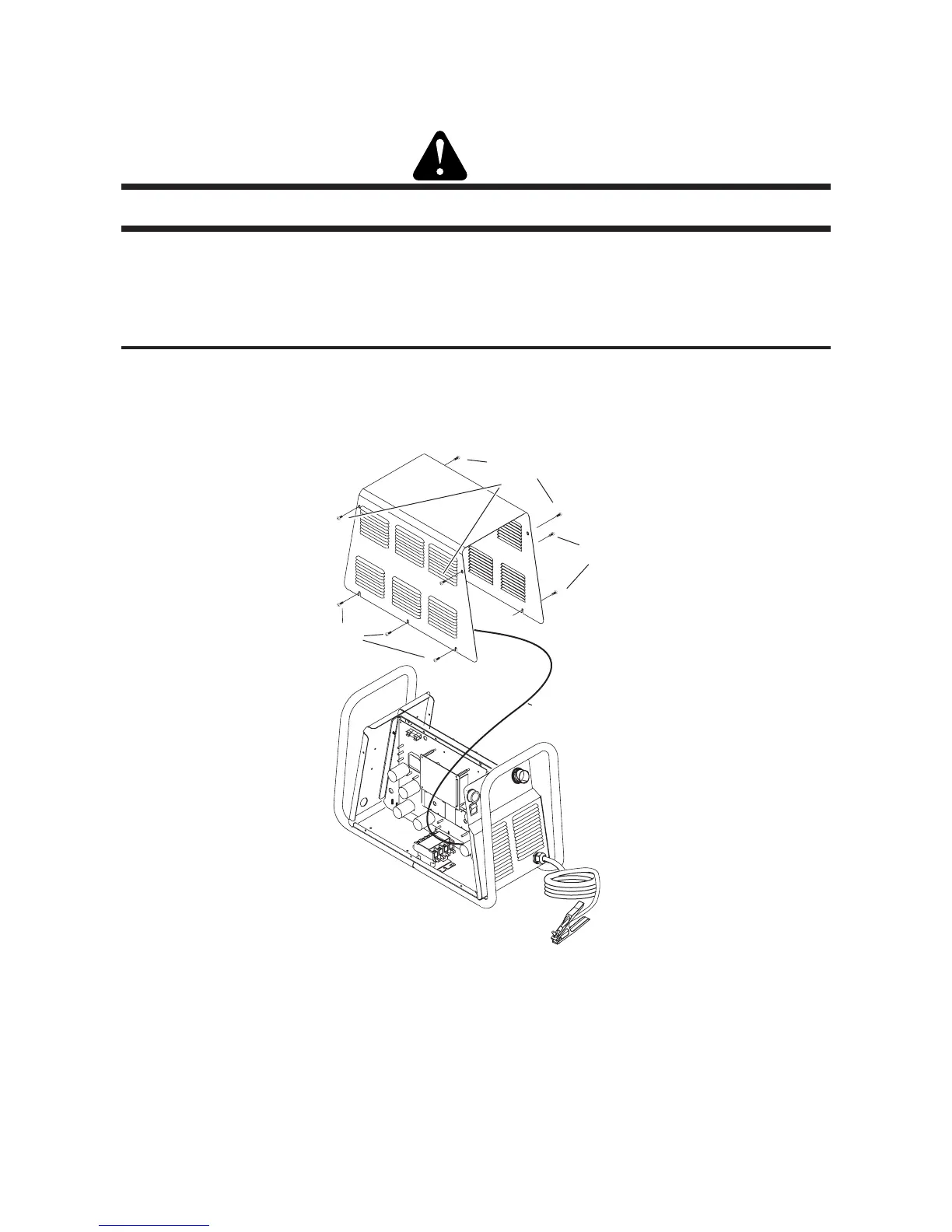
A. Cover Removal
1. Remove the upper screws which secure the cover to the main assembly.
NOTE
There is a ground wire connection to the inside of the unit. There is no need to disconnect the ground wire, unless
there is a need for more room to work.
Art # A-04510
Lower
screws
Upper screws
Ground wire
Lower
screws
2. Loosen, but do not remove, the lower screws, then carefully pull the Cover up and away from the unit.

 Loading...


