Manual 0-4669 5-7 SERVICE
5.03 Front Panel Parts Replacement
WARNING
Disconnect input power at the source and bleed down the system before attempting these procedures.
A. Current (A) Control Knob Replacement
1. Turn the control knob fully clockwise and note the location of the pointer on the knob.
2. Loosen the screw securing the Knob to the potentiometer shaft and remove the Knob.
3. Place the replacement Knob on the potentiometer shaft with the location of the pointer the same as noted in step 1.
4. Tighten the screw to secure the knob to the potentiometer shaft.
B. ON/OFF Switch (SW1) Replacement
1. Remove the power supply cover per Section 5.02-A.
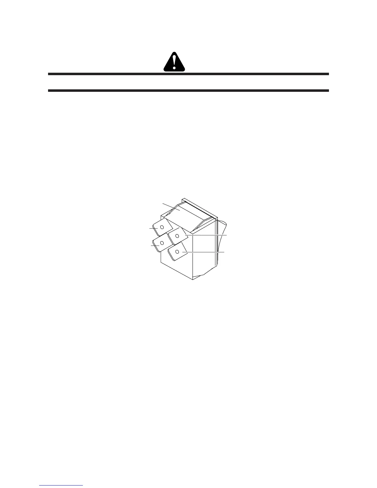
2. Disconnect the wires on the rear of the ON/OFF Switch. Note the location of each wire, as shown below:
Art # A-02774
Wire #21
Wire #24
Top clip
Wire #22
Wire #23
3. Squeeze together the clips on the top and bottom of the Switch. Remove the Switch through the Front Panel.
4. Install the replacement Switch by reversing the above steps.
5. Reinstall the power supply cover.

 Loading...


