CutMaster a120
Manual 0-4989 4T-37 OPERATION
Stainless Steel
40A
Air Plasma / Air Shield
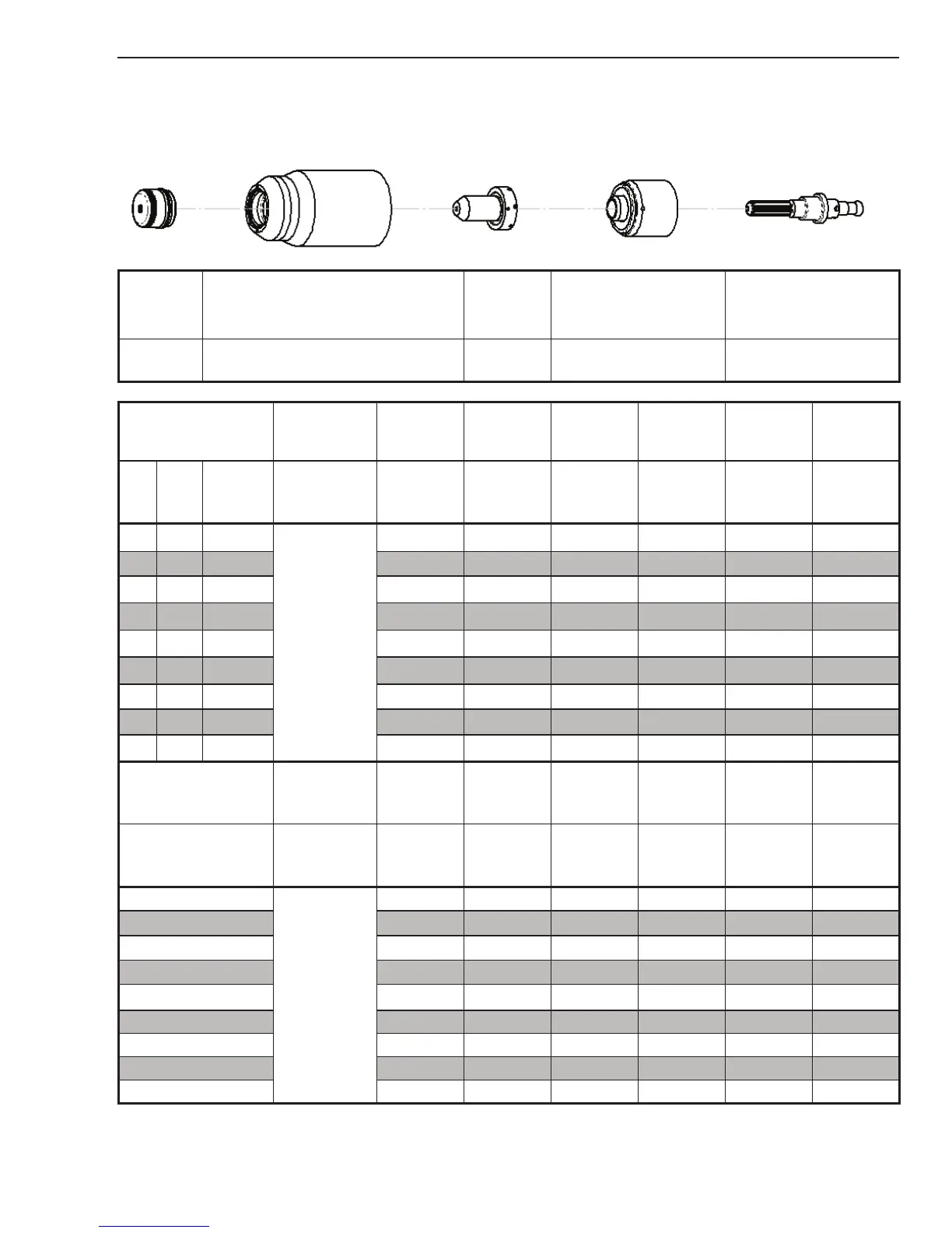
Shield Cap Maximum Life Shield Cup Tip
Starter Cartridge
Heavy Duty Starter
Cartridge
Electrode
9-8245 9-8237 9-8208
9-8213
9-8277
9-8232
Material
Thickness
Gas Pressure
(Air)
Arc Voltage
Torch
Working
Height
Travel Speed
Initial
Piercing
Height
Pierce Delay
Kerf Width
@ Rec.
Speed
(GA)
(in) inch
PSI
(torch lead
length)
Volts
(in)
(ipm) (in) (sec) (in)
18
0.050
75 (25')
80 (50')
110 0.16 60 4.1 0.0 0.06
16
0.063 108 0.16 50 4.1 0.1 0.07
14
0.078 114 0.16 45 4.1 0.1 0.07
12
0.109 113 0.16 40 4.1 0.2 0.07
10
0.141 116 0.16 35 4.1 0.3 0.07
3/16 0.188 115 0.16 30 4.1 0.4 0.07
1/4 0.250 118 0.16 20 4.1 1.2 0.07
3/8 0.375 125 0.16 15 4.1 1.8 0.08
1/2 0.500 127 0.16 10 4.1 2.0 0.08
Material
Thickness
Gas Pressure
(Air)
Arc Voltage
Torch
Working
Height
Travel Speed
Initial
Piercing
Height
Pierce Delay
Kerf Width
@ Rec.
Speed
(mm)
Bar
(torch lead
length)
Volts (mm) (mm/min) (mm) (sec) (mm)
1
5.2 (7.6)
5.5 (15.2)
109
4.1
1670 4.1 0.0 1.7
2
114 4.1 1140 4.1 0.1 1.8
3
114 4.1 980 4.1 0.2 1.8
4
116 4.1 845 4.1 0.3 1.8
5
115 4.1 725 4.1 0.4 1.8
6
117 4.1 565 4.1 0.5 2.0
8
122 4.1 440 4.1 1.5 2.0
10
125 4.1 360 4.1 1.8 2.0
12
127 4.1 280 4.1 2.0 2.2
BOLD TYPE indicates maximum piercing parameters.