CutMaster a120
OPERATION 4T-38 Manual 0-4989
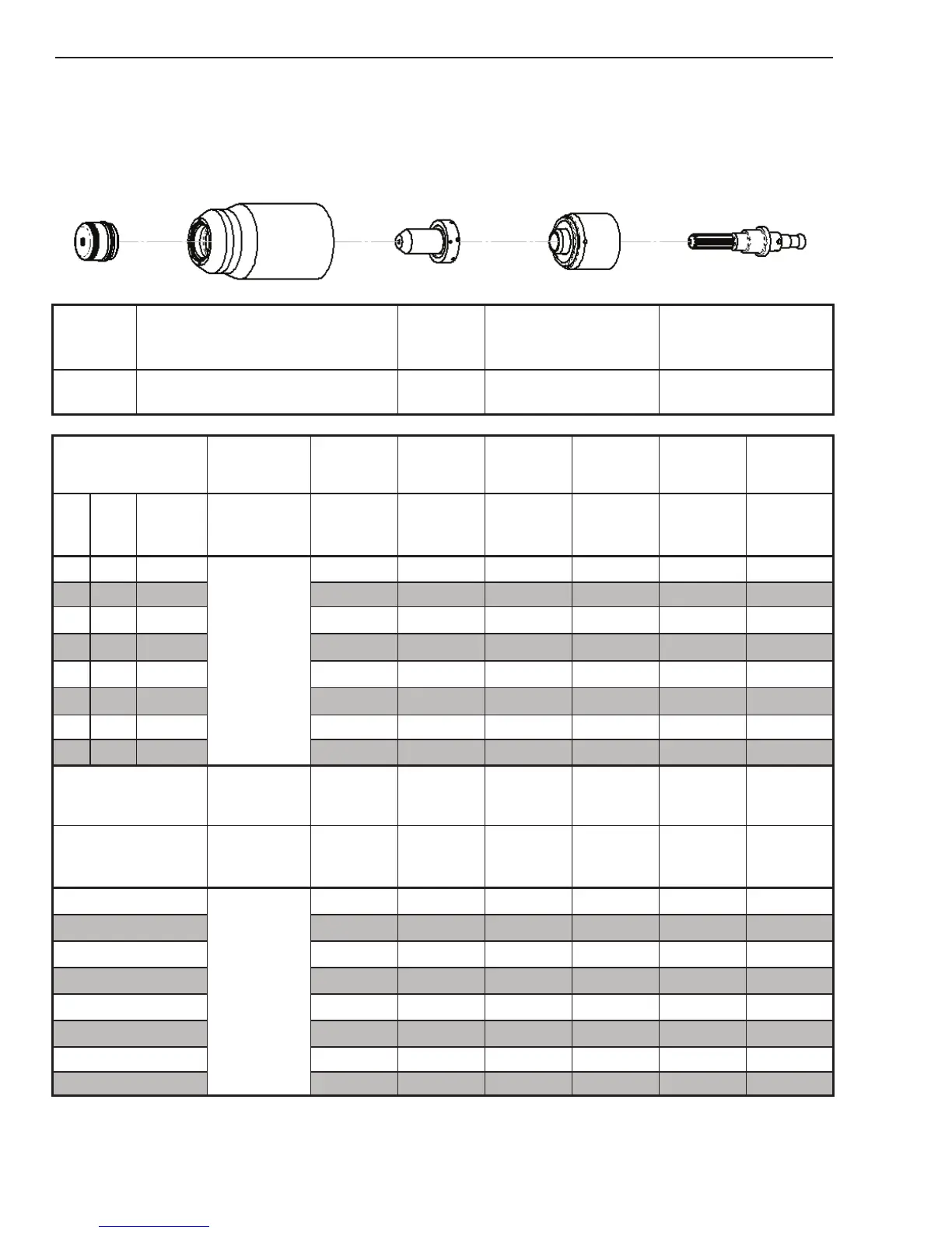
Aluminum
40A
Air Plasma / Air Shield
Shield Cap Maximum Life Shield Cup Tip
Starter Cartridge
Heavy Duty Starter
Cartridge
Electrode
9-8245 9-8237 9-8208
9-8213
9-8277
9-8232
Material
Thickness
Gas Pressure
(Air)
Arc Voltage
Torch
Working
Height
Travel Speed
Initial
Piercing
Height
Pierce Delay
Kerf Width
@ Rec.
Speed
(GA)
(in) inch
PSI
(torch lead
length)
Volts
(in)
(ipm) (in) (sec) (in)
20
0.040
75 (25')
80 (50')
110 0.19 300 0.20 0.0 0.06
16
0.063 113 0.19 170 0.20 0.1 0.07
12
0.097 120 0.19 100 0.20 0.2 0.07
11
0.125 125 0.19 90 0.20 0.3 0.07
9
0.160 126 0.19 85 0.20 0.4 0.07
3/16 0.188 128 0.19 70 0.20 0.5 0.07
1/4 0.250 137 0.19 30 0.20 1.0 0.08
3/8 0.375 145 0.19 10 0.20 2.0 0.09
Material
Thickness
Gas Pressure
(Air)
Arc Voltage
Torch
Working
Height
Travel Speed
Initial
Piercing
Height
Pierce Delay
Kerf Width
@ Rec.
Speed
(mm)
Bar
(torch lead
length)
Volts (mm) (mm/min) (mm) (sec) (mm)
1.0
5.2 (7.6)
5.5 (15.2)
110 4.8 7660 5.1 0.0
1.6
2.0 116 4.8 3490 5.1 0.2
1.8
3.0 124 4.8 2350 5.1 0.3
1.8
4.0 126 4.8 2170 5.1 0.4
1.8
5.0 129 4.8 1630 5.1 0.6
1.8
6.0 135 4.8 990
5.1 1.0
1.9
8.0 141 4.8 500 5.1 1.6 2.0
10.0 146 4.8 180 5.1 2.1 2.3
BOLD TYPE indicates maximum piercing parameters.