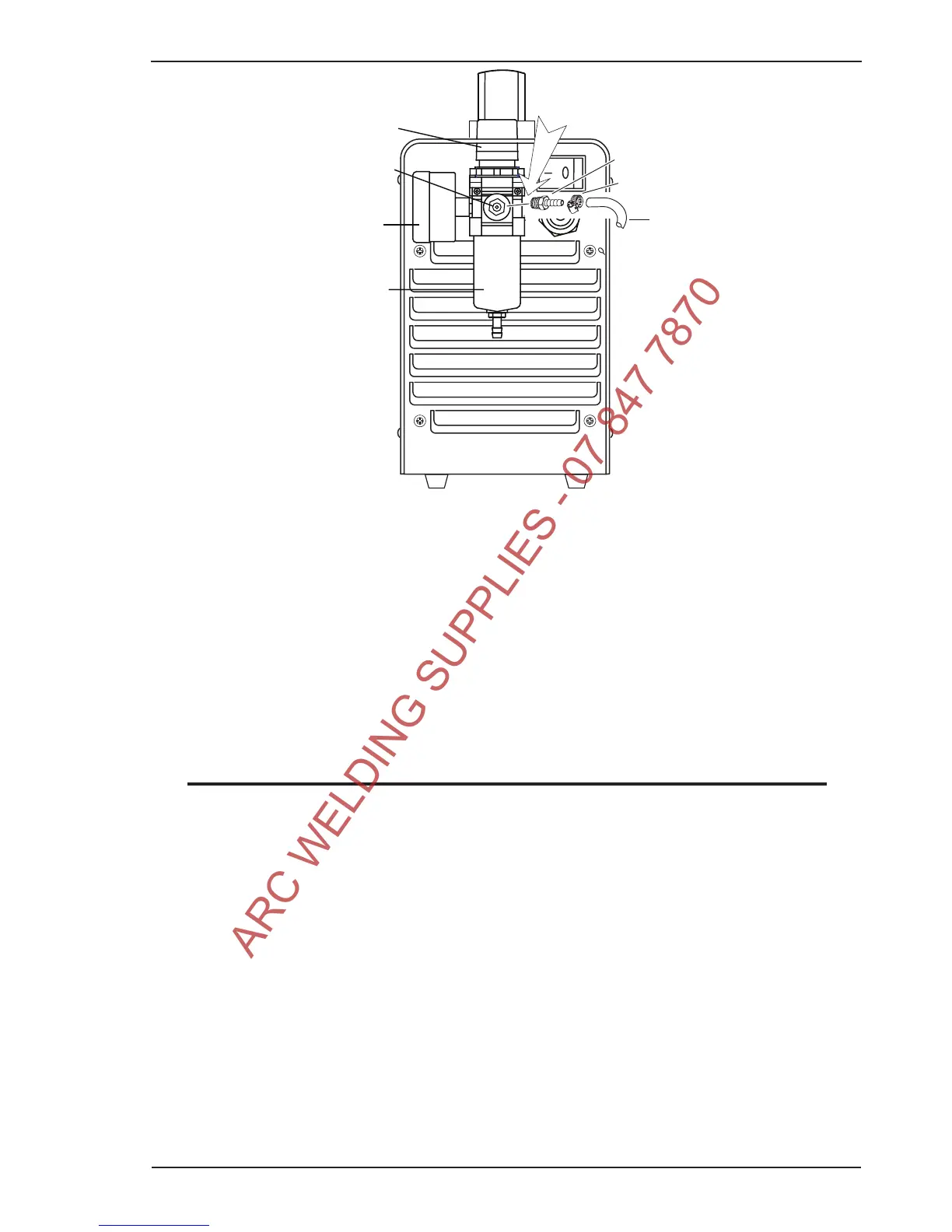
Figure 3-2 Gas Connection to Compressed Air input
B. Using Industrial Compressed Air In Gas Cylinders
When using Industrial compressed air in gas cylinders as the gas supply:
1. Refer to the manufacturer’s specifications for installation and maintenance procedures for high pressure gas
regulators.
2. Examine the cylinder valves to be sure they are clean and free of oil, grease or any foreign material. Briefly
open each cylinder valve to blow out any dust which may be present.
3. The cylinder must be equipped with an adjustable high - pressure regulator capable of outlet pressures up to
100 psi (6.9 bar) maximum and flows of at least 300 scfh (141.5 lpm).
4. Connect gas supply hose to the cylinder.
NOTE
Pressure should be set at 100 psi (6.9 bar) at the high pressure gas cylinder regulator.
Supply hose must be at least 1/4 inch (6 mm) I.D.
For a secure seal, apply thread sealant to the fitting threads, according to manufacturer's instructions.
Do Not use Teflon tape as a thread sealer, as small particles of the tape may break off and block the
small gas passages in the torch.