EasyManuals Logo

Thermal Dynamics cutskill 35A User Manual

Thermal Dynamics cutskill 35A
40 pages
To Next Page IconTo Next Page
To Previous Page IconTo Previous Page
Page #24 background imageLoading...
Page #24 background image
cutSKILL 35A
OPERATION 4-4 June 30, 2009
Gas Pressure Regulator/
Filter Assembly
Gas Pressure Gauge
Art # A-09176
H. Select Current Output Level
Place RUN / SET switch to RUN (up) position. Gas flow will stop. Set the desired current output level.
Art # A-09181
RUN
SET
CURRENT (A)
15
25
35
READY
AIR OVERHEAT
POWER
4.03 Sequence of Operation
The following is a typical sequence of operation for this power supply. Refer to Appendix 1 for block diagram.
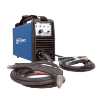
1. Plug the input power cord into an active circuit.
a. AC power is available at the power supply.
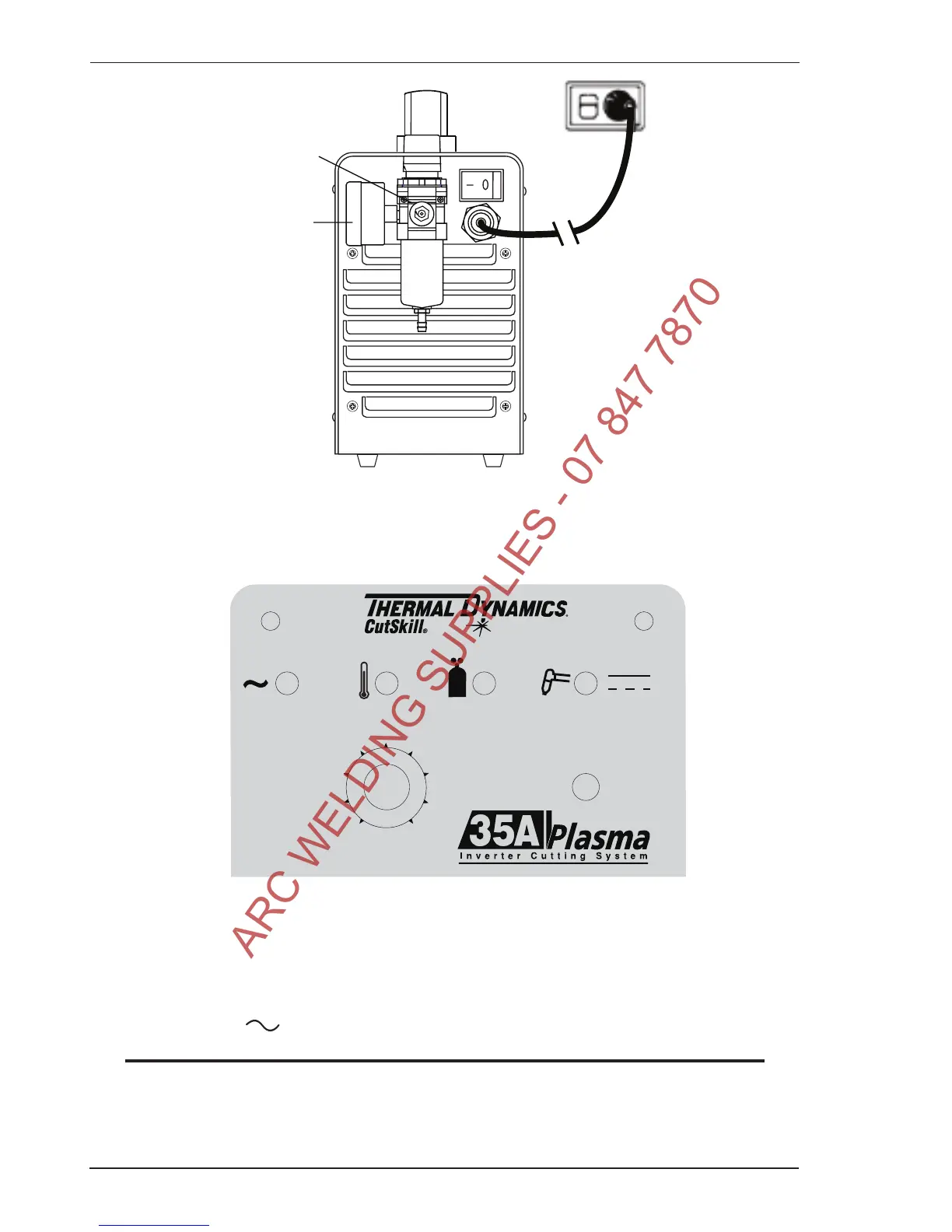
2. Place the ON / OFF switch on the power supply to ON (up) position.
a. AC indicator turns on; fan turns on.
NOTE
Gas will automatically flow from torch for 4 seconds, this is a safety circuit that makes sure the torch
tip is properly installed.
3. Set gas pressure.
a. Turn gas pressure adjustment knob to set pressure to 65 psi / 4.5 bar.
ARC WELDING SUPPLIES - 07 847 7870

Questions and Answers:

Question and Answer IconNeed help?

Do you have a question about the Thermal Dynamics cutskill 35A and is the answer not in the manual?

Thermal Dynamics cutskill 35A Specifications

General IconGeneral
BrandThermal Dynamics
Modelcutskill 35A
CategoryWelding System
LanguageEnglish

Related product manuals