cutSKILL 35A
June 30, 2009 4-3 OPERATION
C. Check Primary Input Power Source
1. Check the power source for proper input voltage. Make sure the input power source meets the power
requirements for the unit per Section 2, Specifications.
2. Connect the input power cable (or close the main disconnect switch) to supply power to the system.
D. Gas Selection
Ensure gas source meets requirements listed in section 2T. Check connections and turn gas supply on.
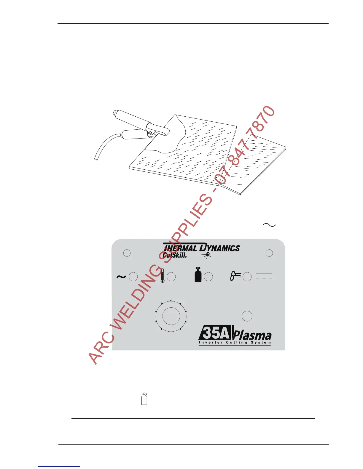
E. Connect Work Cable
Clamp the work cable to the workpiece or cutting table. The area must be free from oil, paint and rust. Con-
nect only to the main part of the workpiece; do not connect to the part to be cut off.
Front Panel With Power ON/OFF Indicator
G. Set Operating Pressure
Place the power supply RUN / SET switch to the SET (down) position. Gas will flow. Adjust gas pressure to
65 psi / 4.5 bar. Air indicator turns on.
NOTE
If gas regulator leaks, reset gas pressure to 0 psi, then reset to 65 psi / 4.5 bar.