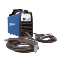
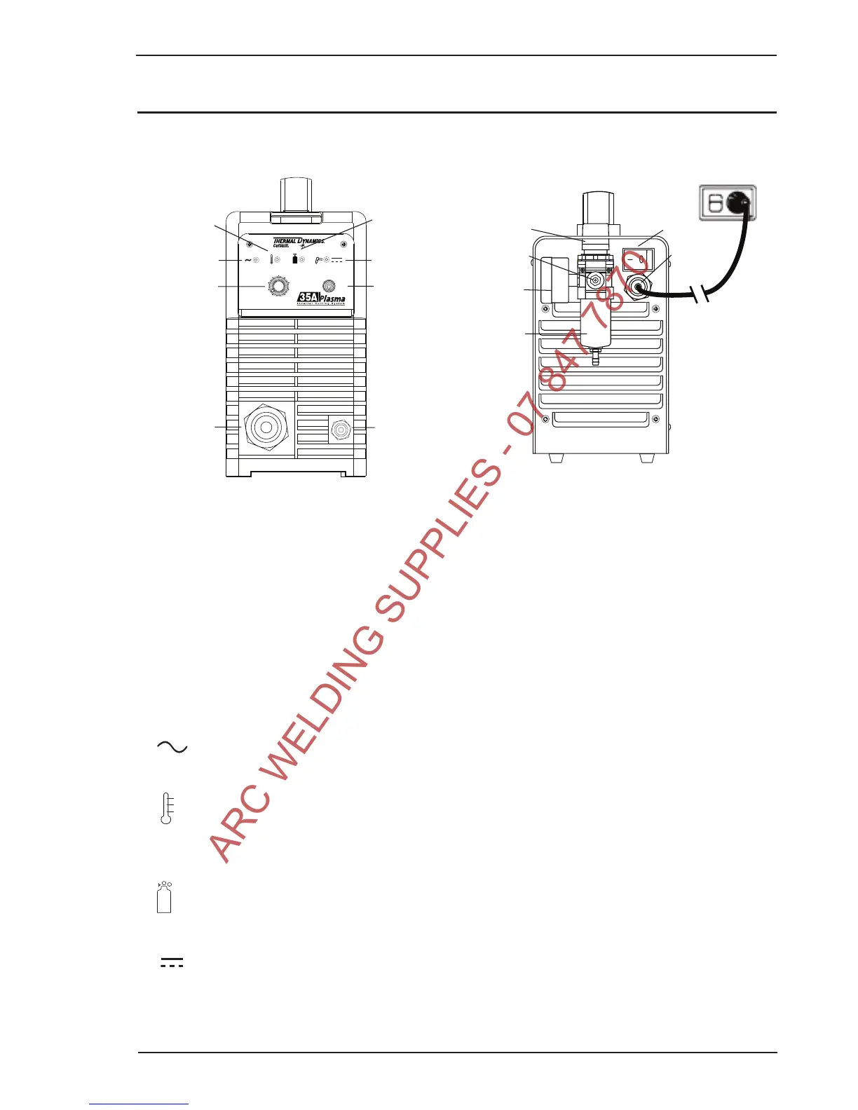
The Front Panel The Rear Panel
1. ON / OFF Switch (Power Switch)
Controls input power to the power supply. I is ON, O is OFF.
2. RUN / SET Switch
RUN (up) position is for general torch operation. SET (down) position is for setting gas pressure and
purging lines.
3. (A) Output Current Control
Sets the desired output current. If the overload protection (fuse or circuit breaker) on the input power
circuit opens frequently, either reduce cutting output, reduce the cutting time, or connect the unit to more
adequate input power. Refer to Section 2 for input power requirements.
4.
Power ON Indicator (AC Indicator)
Steady light indicates power supply is ready for operation.
5.
OVERHEAT Indicator (TEMP Indicator)
Indicator is normally OFF. Indicator is ON when internal temperature exceeds normal limits. Allow the unit
to run with the fan on until the temp indicator turns off.
6.
AIR Indicator
AIR light should be ON when there is insufficient gas pressure (below 50 psi).
7.
READY (DC Indicator)
Indicator is ON when DC output circuit is active.