Manual 0-2888 3-3 INSTALLATION
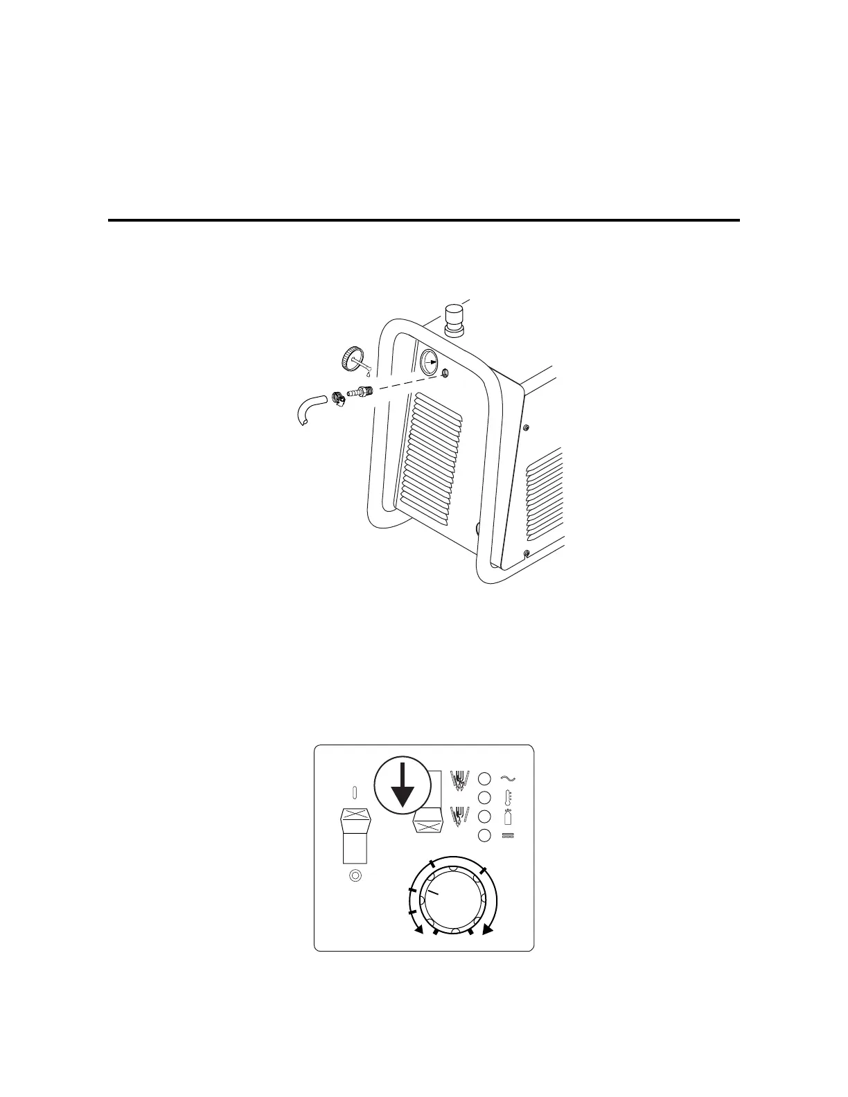
3.4 Gas Connections
A. Connecting Gas Supply to Unit
The connection is the same for compressed air or high pressure gas cylinders. Refer to subsection 3.4-C if an optional
air line filter is to be installed.
1. Connect the gas line to the inlet port. The illustration shows typical fittings as an example.
NOTE
For a secure seal, apply thread sealant to the fitting threads, according to manufacturer's instructions. Do Not use
Teflon tape as a thread sealer, as small particles of the tape may break off and block the small gas passages in the torch.
A-03272
Min. 1/4 inch
6.4 mm
Gas Connection to Inlet Port
B. Check Air Quality
To test the quality of air, put the RUN / SET switch in the SET (down) position, place a welding filter lens in front of
the torch and turn on the gas. Any oil or moisture in the air will be visible on the lens. Do not start an arc!
A-03385
A
3020
26
28
24
22