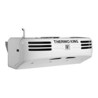
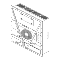
Electrical Maintenance
67
Initiating the Defrost cycle energizes the Zone 2
defrost relays, RD and RDR4. When RD is
energized, it energizes the RHGS circuit, which
energizes the RHGS and the 26 circuit. The 26
circuit energizes the CIS (and the RTPS and PV
when the RTPC is closed). When RDR4 is
energized, it opens the RLLS-REFR circuit,
which de-energizes the Zone 2 evaporator fans.
During Defrost the Zone 2 TG-V Controller
energizes the R10 circuit, which forces the
condensing unit to run in high speed.
The CIS and RHGS divert heated refrigerant
vapor to the evaporator coil, melting frost.
De-energizing the evaporator fans keeps the heat
in the evaporator and prevents warm air from
passing over the load.
The defrost termination switch will open and
de-energize the defrost relays when the frost has
melted and the evaporator temperature rises above
52 F (11 C). The TG-V Controller then determines
the mode of operation.
Zone 2 Evaporator Defrost Cycle
Electric Operation
The Defrost cycle on electric standby operation is
similar to the Defrost cycle on diesel operation.
Zone 2 Evaporator Defrost Cycle
Checkout Procedure
To check the Defrost cycle, run the Zone 2
evaporator on Cool until the evaporator coil
temperature is below 42 F (6 C). Press the
MANUAL
D
EFROST key.
If the Zone 2 evaporator shifts to Defrost
momentarily but shifts out of Defrost when the
key is released, check the TG-V controller. See
“Field Test Procedure for Multi-Temperature
In-Cab TG-V Controllers” on page 75.
If the Zone 2 evaporator will not shift to Defrost,
or if the Defrost cycle will not terminate, see the
following Defrost checkout procedures.
Zone 2 Evaporator Does Not Defrost
1. Check the evaporator temperature:
Make sure the evaporator temperature is
actually below 42 F (6 C) if the unit will not
Defrost. Use a test thermometer to check the
evaporator temperature.
2. Check the operation of the defrost termination
switch:
If the unit fails to Defrost, place a jumper wire
between the R12 circuit and the CH circuit at
the defrost termination switch. Press the
MANUAL DEFROST key. If the unit shifts to
Defrost, check for a defective defrost
termination switch. If the unit still fails to
Defrost, move to step 3.
3. Check for an open in the R12 circuit between
the defrost termination switch and the TG-V
controller. If the 12 circuit is not open, move
to step 4.
4. Check for an open in R11 circuit between the
TG-V Controller and the defrost relay. If the
R11 circuit is not open, move to step 5.
5. Check the defrost relays:
If the unit fails to Defrost, check the R8NN
circuit at RD and the 88 circuit at RDR4 for
12 volts dc. If the circuit has 12 volts, the
defrost relay is defective and should be
replaced. A lack of voltage indicates an open
in the R8NN or 88 circuit.
6. If the defrost relays energize, the defrost
indicator light comes on and the fans stop, but
the unit continues to cool; check the CIS, the
26 circuit, the RHGS, and the RHGS circuit.