Engine Maintenance
91
Electrical Changes
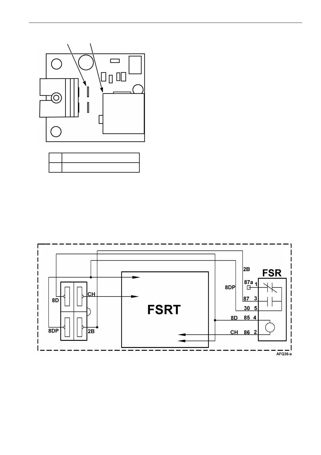
The fuel solenoid timer and fuel solenoid relay are
located on a PC board. This improves reliability
and simplifies the wiring. The PC board is
mounted on the side of the control box to the left
to the multi-temp relay board
The size of the capacitor has been changed to
increase the pull-in time from 1 second to 2
seconds. This minimizes the chance that the
pull-in coil would fail to open the fuel valve. The
integral fuel solenoid contains two coils: the
pull-in coil, and the hold-in coil. The pull-in coil
draws approximately 30 to 40 amps at 12 volts.
The hold-in coil draws approximately 1 amp at 12
volts.
The pull-in coil must be energized to move the
injection pump governor linkage to the fuel on
position. Once the injection pump governor
linkage has been moved to the fuel on position,
the hold-in coil will keep it in fuel on position
until the 8D circuit is de-energized. The pull-in
coil must be de-energized after the 2 second
pull-time.
The timer now turns off instantly because the
capacitor discharges through the hold-in coil in
the fuel solenoid (8D circuit). This minimizes the
chance that the timer would fail to energize the
fuel solenoid relay after the unit had been turned
off momentarily. The earlier timer required the
unit to be turned off for at least 3 seconds to
discharge the capacitor.
Figure 45: Wiring Diagram of Fuel Solenoid Timer Starting 4th Quarter 97
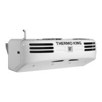
1. Four Pin Connector
2 Fuel Solenoid Relay (FSR)
Figure 44: Fuel Solenoid Timer
1
2
AGA337