Engine Maintenance
93
b. Momentarily energize the pull-in coil by
placing a jumper between the 8DP pin in
the fuel solenoid and the 2 terminal at the
control circuit. The fuel solenoid should
make a definite click when the pull-in coil
is energized, but should not click when the
pull-in coil is de-energized.
c. De-energize the hold-in coil by removing
the jumper from the 8D terminal. The fuel
solenoid should make a definite click
when the hold-in coil is de-energized.
d. If the hold-in coil does not function
properly, check the resistance of the
hold-in coil by placing an ohmmeter
between the 8D pin and the CH pin in the
fuel solenoid. The resistance of the hold-in
coil should be approximately 24 ohms. If
the resistance of the hold-in coil is not in
this range, replace the fuel solenoid.
e. If the hold-in coil does function properly,
go to step 9.
9. Reconnect the fuel solenoid wire connector to
the fuel solenoid.
10. Remove the fuel solenoid relay from its socket
and make sure the unit is turned On.
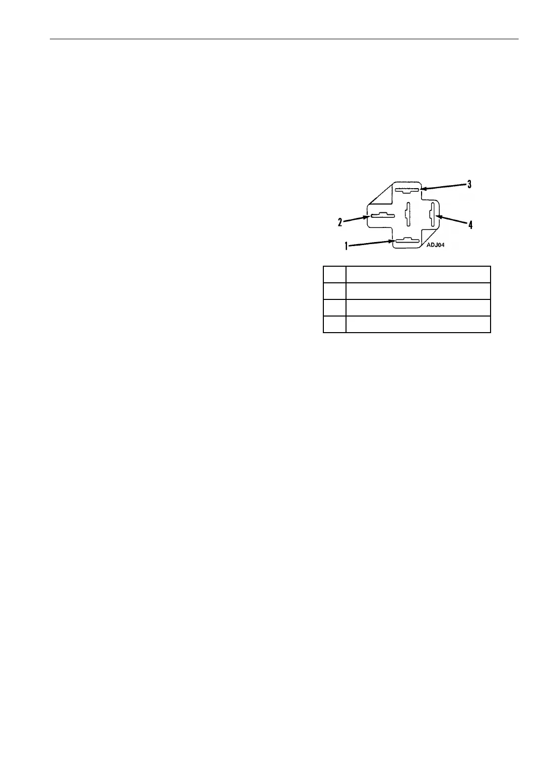
11. Check the voltage on the 8D circuit at the 85
terminal in the fuel solenoid relay socket.
Refer to the following illustration to identify
the terminals in the relay socket.
a. If battery voltage is not present on the 8D
circuit, check the 8D circuit for an open or
a short (minimum voltage is 10 volts).
b. If battery voltage is present on the 8D
circuit, go to step 12.
12. Check the voltage on the 2B circuit at the 30
terminal in the fuel solenoid relay socket.
a. If battery voltage is not present on the 2B
circuit, check the 2B circuit for an open or
a short.
b. If battery voltage is present on the 2B
circuit, go to step 13.
13. Test the relay.
a. Use a jumper to connect the 85 terminal
on the relay to the 2 terminal at the control
circuit.
b. Use another jumper to connect the 85
terminal on the relay to the 2 terminal at
the control circuit.
c. If the relay does not energize, it is
defective. Replace the relay.
d. If the relay does energize, the timer is
defective. Replace the fuel solenoid timer
PC board.
14. Remember to reconnect the 20 wire to the
reset switch.
1. 86 Terminal—8DC Circuit
2. 30 Terminal—2B Circuit
3. 85 Terminal—8D Circuit
4. 87 Terminal—8DP Circuit
Figure 47: Relay Socket Terminal Identification