Wiring
Detector Signal Wiring
All signals from the detector are wired to the VPI board that is installed in
the transmitter slot PCB 4. Refer to the appropriate installation wiring
drawings for the detailed requirements.
Detector Signal
Wiring
etector Signal
Wiring
● 868680-2: Installation wiring, 1400A/1400S transmitter
● 868577: Installation wiring, 9719B/9720B scintillation detector
● 868697: Installation wiring, 9701/9702 ion chamber detector
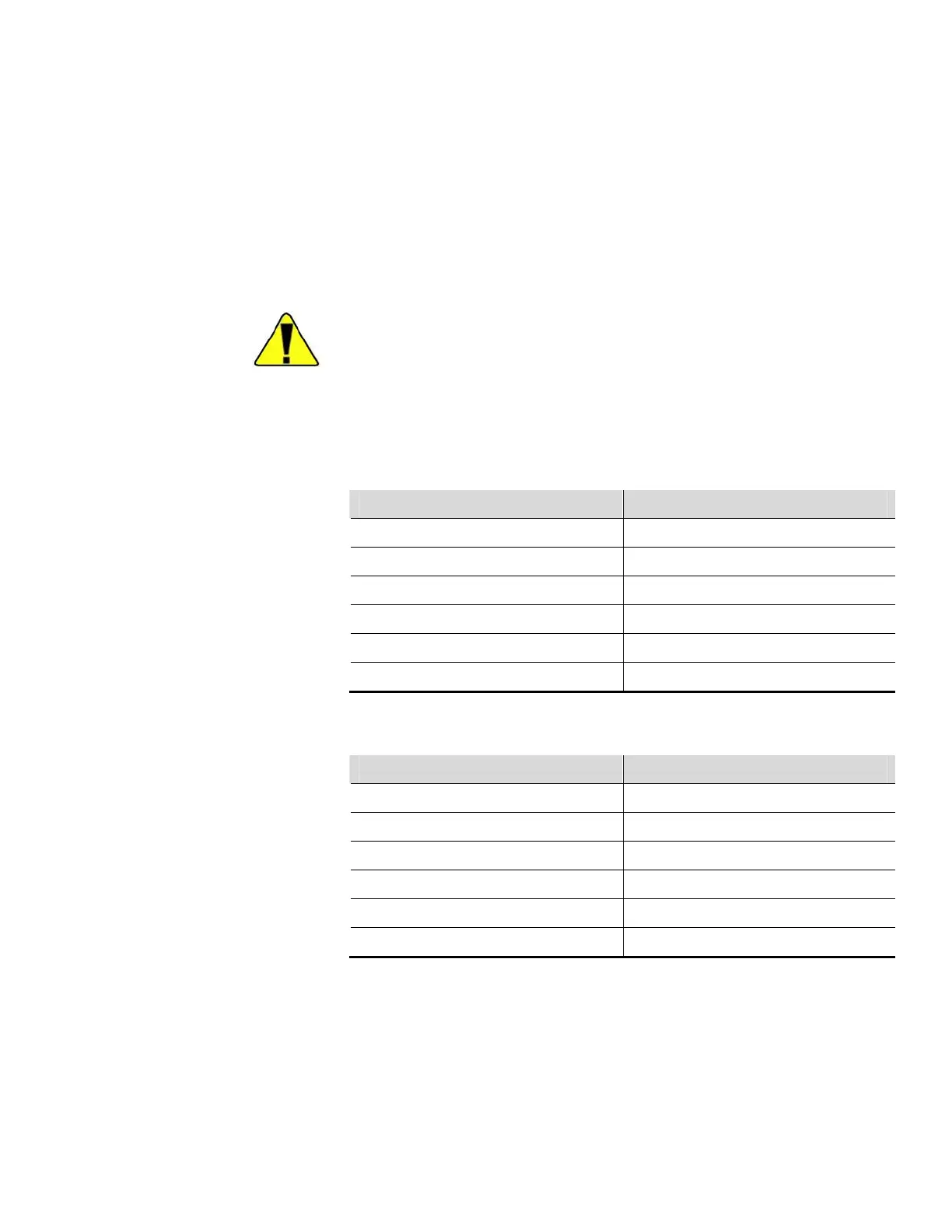
Caution Remove power from the transmitter before changing jumper
settings. Failure to do so may result in damage to the VPI board. ▲
Signal wiring for the 9719B/9720B scintillation detectors are shown in the
tables below. Use 22–16 AWG individually shielded cable (1000 ft
maximum).
Table 4–5. Wiring for scintillation detector data and references pulses
Scintillation Adaptor Board VPI Board in 1400A/1400S Transmitter
J2-1 (DATA (H)) J1B-15 (+PULSE DATA)
J2-2 (SHIELD) J1B-21 (SHIELD)
J2-3 (DATA (L)) J1B-16 (-PULSE DATA)
J2-4 (REF (H)) J1B-17 (+PULSE REF)
J2-5 (SHIELD) J1B-21 (SHIELD)
J2-6 (REF (L)) J1B-18 (-PULSE REF)
Table 4–6. Wiring for scintillation detector HV pulses or duty cycle mode
Scintillation Adaptor Board VPI Board in 1400A/1400S Transmitter
J3-1 (INC (H)) J1B-19 (+HV INCREASE)
J3-2 (SHIELD) J1B-24 (SHIELD)
J3-3 (INC (L)) J1B-20 (-HV INCREASE)
J3-4 (DEC (H)) J1B-22 (+HV DECREASE)
J3-5 (SHIELD) J1B24 (SHIELD)
J3-6 (DEC (L)) J1B-23 (-HV DECREASE)
Thermo Fisher Scientific DensityPRO+ Installation Guide 4-11