English
5
- If you are going to use external USB HDD (Hard Disk Drive) please consider that the power
specications might exceed the supported output of your receiver (5 V/800 mA). If so, please
connect your USB HDD to an according external power adapter.
- STRONG cannot guarantee compatibility with all types of USB storage devices.
- It is advised not to store important information on USB storage devices used with the receiver.
Always make backups of data on your USB storage device before using it with this receiver. STRONG
will not take responsibility for any loss of information or circumstances caused by loss of information.
- Please ensure that either the USB device is already formatted to NTFS or FAT32 or format the USB
device via your receiver. Formatting requires entering the PIN code (default 0000)
- STRONG cannot guarantee the playback of all les although extensions are listed, as it depends on
le size, codec, bit rate and resolution.
2.0 YOUR RECEIVER
2.1 DEFAULT PIN-CODE: 0000
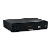
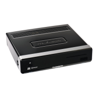
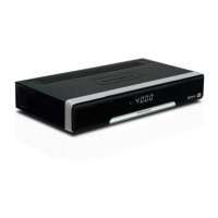
2.2 Front Panel
Fig.1
1. Power button Switch the receiver to Standby or On
2. P-/P+: To change channels without using the remote control
3. LED Display Displays channel number, time, videotext page or recording modes
4. Standby indicator: Shows power state of the receiver: Red LED - receiver is in standby
mode
5. USB To connect your USB storage device
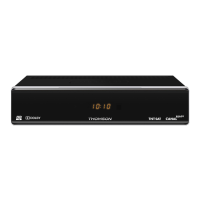
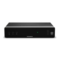
2.3 Side Panel
Fig.2
1. Smart card slot To insert your HD+ smart card with the golden chip facing down.
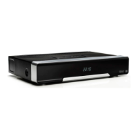
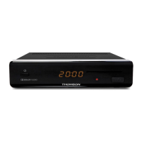
2.4 Rear Panel
Fig. 3
1. SAT IN To connect to the LNB of your satellite antenna for reception of
satellite broadcast signal
2. S/PDIF (coax.) To connect to a digital amplier or home theatre using a coaxial
cable
3. HDMI To connect to the HDMI input of your TV set using a good quality
HDMI cable
4. TV SCART To connect to TV using a SCART cable
5. Ethernet To connect to a network switch, router or modem
6. DC POWER To connect to the original included main power adapter (Input
~230 V 50~60 Hz/ Output 12 V, 1.5 A DC
)
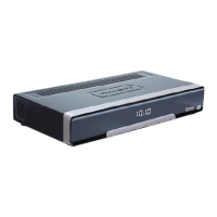
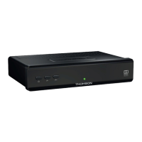
2.5 Remote Control
Fig. 4
1. q Turns the receiver ON/Standby
2. ! To turn the sound on or off
3. 0~9 Channel number and numeric value input
4. TV/R Toggles between TV and radio mode
5. No function
6. FAV To access your favourite channels. Toggles between available
favourite groups
7. 9 To switch between the last viewed channels
8. AUDIO Displays the audio selection menu with selections for available
languages and audio modes