16 HA0338T Rev C July 2022
Chapter 4
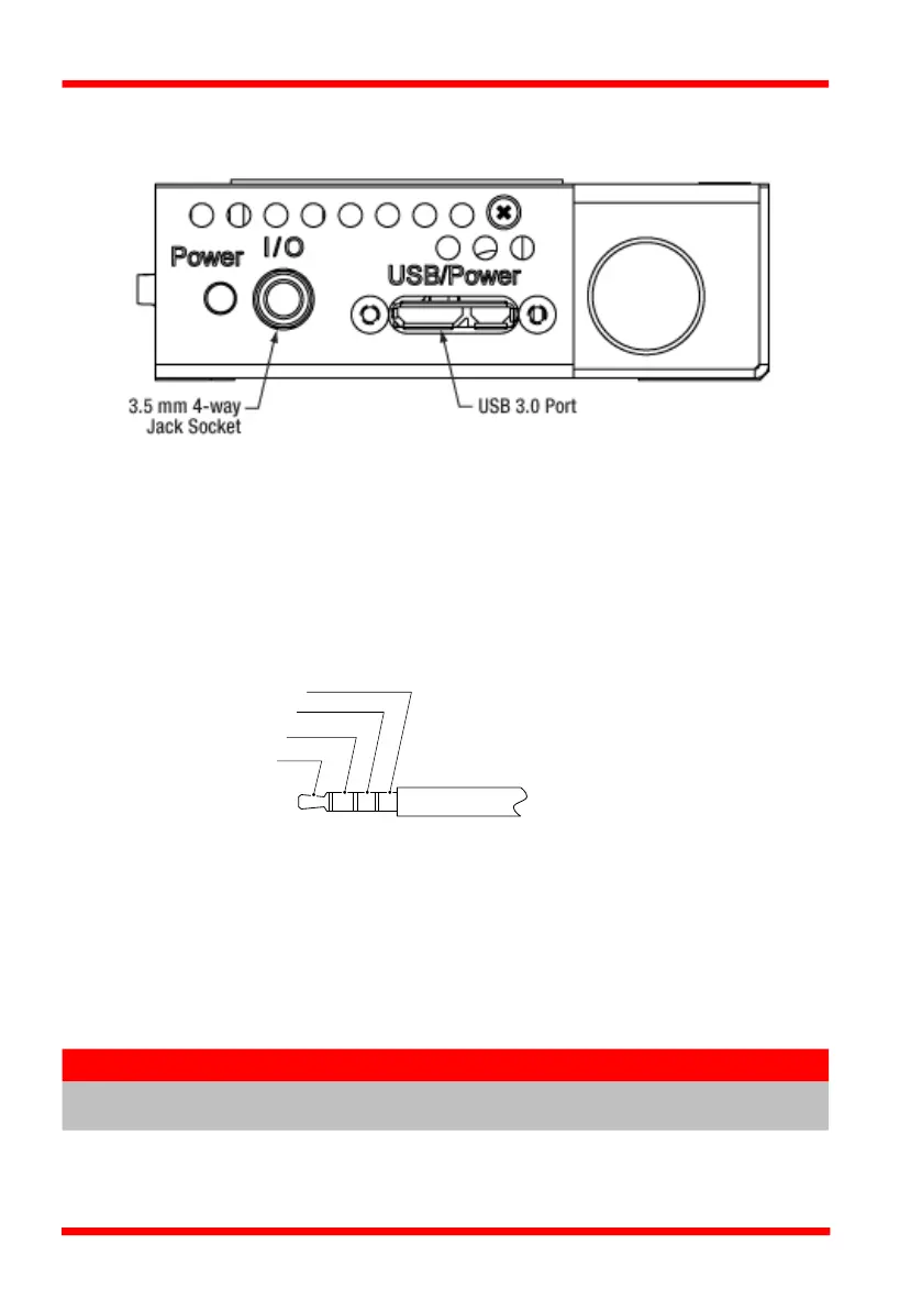
4.3 Connector Detail
The side of the unit is fitted with a number of connectors as shown below:.
Fig. 4.1 Power and USB Connectors
USB/Power - Provides connection to the PC USB port or the USB hub. Although the
port is designed to mate with a USB 3.0 connector, it can also be used with a ‘USB
Micro B’ type connector, which plugs into the left hand side shown shaded above.
Power LED - Green LED, lit when power is applied to the unit.
I/O - 3.5 mm 4-way jack socket, provides connection to an external Trigger IN/Out
source. Pin out is as shown below.
Fig. 4.2 I/O Pin Out Detail
4.4 Connecting The Hardware
1) Perform the mechanical installation as detailed in Section 3.
2) Install the APT Software - see Section 4.1.
3) Using the USB cable provided, connect the stage unit to your PC or a powered
USB hub.
The USB connection provides both power and comms. When power is applied, the
green ‘Power’ LED is lit.
Note
The USB cable should be no more than 3 metres in length. Communication
lengths in excess of 3 metres can be achieved by using a powered USB hub).
Pin 4 - Fused +5 V
Pin 3 - Gnd (0 V)
Pin 2 - Trig In
Pin 1 - Trig Out

 Loading...


