26 HA0338T Rev C July 2022
Chapter 5
5.10 Graphical Control Of Motor Positions (Point and Move)
The GUI panel display can be changed to a graphical display, showing the position of
the motor channel(s). Moves to absolute positions can then be initiated by positioning
the mouse within the display and clicking.
To change the panel view to graphical view, right click in the screen and select
‘Graphical View’.
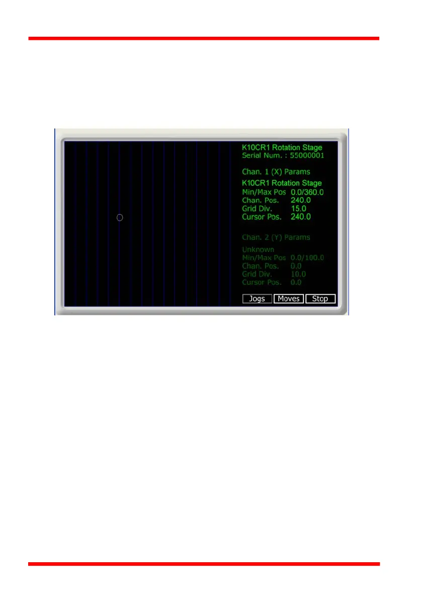
Fig. 5.7 K10CR1 Stage GUI Panel - Graphical View
Consider the display shown above for a K10CR1 Integrated Stage.
The right hand display shows the channel and motor unit parameters; i.e. controller
unit type and serial number, stage type, minimum and maximum positions, current
position, units per grid division and cursor position. All units are displayed in real world
units, i.e. millimetres.
Note. For single channel units such as the K10CR1, the Channel 2 parameters are
greyed out.
The left hand display shows a circle, which represents the current position of the stage
associated with the ActiveX Control Instance (absolute position data is displayed in
the 'Chan Pos' field).
The vertical divisions relate to the travel of the associated stage. For example, the
screen shot above shows the parameters for a K10CR1 rotation stage. The graph
shows 15 divisions in the X axis, which relates to 24° of travel per division.
The graphical panel has two modes of operation, ‘Jog’ and ‘Move’, which are selected
by clicking the buttons at the bottom right of the screen.

 Loading...


