EasyManua.ls Logo

THORLABS K10CR1 User Manual

THORLABS K10CR1
69 pages
To Next Page IconTo Next Page
To Previous Page IconTo Previous Page
Page #31 background imageLoading...
Page #31 background image
31
K10CR1 Cage Rotation Stage
5.12 Minimum and Maximum Position Settings
There are no mechanical end stops on the K10CR1 stage and theoretically, the total
(accumulative) angle of the motion could be arbitrarily large. In practice, however, the
integer arithmetic used for the position counter poses a restriction on the range of
position values that can be represented. To avoid integer overflow and underflow
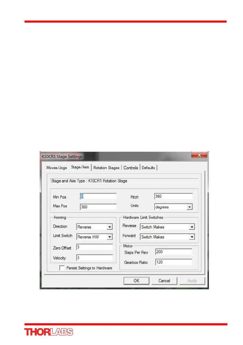
problems, the target position is checked against the limits displayed in the Min Pos
and Max Pos values. This check is done to ensure that the position counter always
shows a correct value. For the K10CR1 stage, the Min Pos and Max Pos limits are
equivalent to around ±43 full rotations (15,480 degrees).
In applications where continuous rotation is required, the Move At Velocity command
can be used. This command does not constrain the angle to the Min Pos and Max Pos
range and the continuity of the movement will not be interrupted until a Stop command
is issued. However, when the integer representing the position counter overflows, the
position value will flip sign and will no longer be correct. Any application commanding
continuous moves for long period of times must take this into account and accept that
once the Min Pos and Max Pos position is exceeded, the value displayed may no
longer be correct. Homing the stage will zero the position count and correct the
display.
Fig. 5.14 K10CR1 Stage/Axis Settings Tab
Question and Answer IconNeed help?

Do you have a question about the THORLABS K10CR1 and is the answer not in the manual?

THORLABS K10CR1 Specifications

General IconGeneral
BrandTHORLABS
ModelK10CR1
CategoryMeasuring Instruments
LanguageEnglish

Summary

Chapter 1 For Your Safety

Safety Information and Symbols

Explains safety symbols and general warnings for safe operation.

General Operational Warnings

Details warnings regarding improper use, fluid spillage, indoor use, and unexpected stage movement.

Chapter 2 Overview

K10CR1 Introduction

Introduces the K10CR1 as a motorized rotation mount accepting Ø1" optics and SM1 components.

APT Software Suite Overview

Describes the APT software suite, including GUI, ActiveX controls, and developer benefits.

APTUser Utility Guide

Explains the APTUser application for interacting with APT hardware control units.

APT Configuration Utility

Details the APTConfig utility for setting system parameters and configurations offline.

APT Server and ActiveX Controls

Explains APT Server and ActiveX Controls for developing custom applications and controlling hardware.

Software Upgrade Information

Information on obtaining the latest software upgrades from the Thorlabs website.

Chapter 3 Mechanical Installation

Unpacking and Handling Precautions

Instructions on retaining packing material and handling the stage carefully.

Environmental Operating Conditions

Specifies operating limits for location, altitude, temperature, and humidity for safe operation.

Stage Mounting Options

Details methods for mounting the stage using posts, adapter plates, and threaded holes.

Transportation and Packing

Guidelines for packing the unit securely for shipping, using original or suitable packaging.

Mechanical Dimensions

Provides detailed dimensional drawings and measurements for the K10CR1 stage.

Chapter 4 Software & Electrical Installation

APT Software Installation Guide

Provides instructions for downloading and installing the APT software, with cautions.

Power Supply Requirements

Explains power sources via USB and considerations for avoiding overload or voltage dips.

Connector Port Identification

Illustrates and describes the Power, USB/Power, and I/O connectors on the unit.

Hardware Connection Procedure

Step-by-step guide for connecting the stage to the PC via USB after installation.

Software Operation Verification

Guides on verifying the APTUser utility, checking stage type, serial number, and jog functionality.

Chapter 5 Operation

Operational Tutorial Introduction

Introduces a tutorial for typical moves and parameter adjustments using APT software.

Standalone Button Operation

Explains basic operation using the unit's top face buttons, with LED descriptions.

Side Panel Button Controls

Details how to use the unit's side panel buttons for motor control functions.

Button Mode: Go to Position

Explains programming buttons to move to specific positions.

Button Mode: Jogging

Describes configuring buttons for 'jog' motor movement.

Using the APT User Utility

Guides on interacting with APT hardware via the APTUser application for control and setup.

Motor Homing Procedure

Explains the homing process to establish a datum and reset the position counter.

Absolute Position Moves

Instructions for moving the stage to a specific angular position via the GUI.

Stopping Stage Movement

How to enable/disable drive channels and stop the stage using the 'Stop' button.

Adjusting Motor Parameters

Details modifying motor parameters like Max Vel and Accn/Dec in the Settings panel.

PC Jogging Control

Explains PC-based jogging using GUI arrow keys in 'Single Step' or 'Continuous' modes.

Graphical Position Monitoring

Using the GUI's graphical view for monitoring position and initiating moves.

Setting Up Move Sequences

How to set up sequences of moves for automated operation using the Move Sequencer.

Position Limit Configuration

Explains Min/Max Pos limits to prevent integer overflow and their effect on continuous rotation.

Simulated Configuration Setup

Guide to setting up simulated hardware configurations for offline development using APT Config.

Chapter 6 Software Reference

Software Reference Introduction

Explains parameters and settings accessed via the APT software on a PC.

GUI Panel Functionality

Shows and describes the Graphical User Interface (GUI) for the stepper controller.

Settings Panel Configuration

Describes the Settings window for modifying motor operation parameters.

Moves and Jogs Settings

Details settings for move and jog velocities, acceleration, and operating modes.

Stage and Axis Settings

Explains settings related to stage type, axis, homing, and motor characteristics.

Rotation Stage Settings

Configures absolute position reporting modes and panel display move directions.

Controls Tab Configuration

Settings for button control modes (Jogging, Go to Position) and hardware triggering.

Default Parameter Reset

Allows resetting all parameter values to factory defaults.

Appendix A Specifications

Stage Performance Specifications

Lists key specifications like travel range, speed, acceleration, repeatability, and accuracy.

Design and Physical Specifications

Details design parameters including base material, bearing type, drive mechanism, and dimensions.

Load Capacity and Stiffness

Outlines load capacity, torque, and stiffness specifications for the stage.

Appendix C Stepper Motor Operation

Stepper Motor Working Principle

Explains the general principle of stepper motor operation and microstepping.

Move Direction Conventions

Defines positive and negative moves for linear and rotational stages.

Velocity Profile Types

Describes velocity profiles like Trapezoidal and S-curve for motor movement.

Stage Positioning Concepts

Explains motion units, microsteps, and the concept of home position.

Home Position Establishment

Details how the home position is established and its importance for setting a datum.

Limit Switch Functionality

Describes the function of microswitches in linear and rotary stages.

Motor Power Saving Modes

Explains power saving features, 'Move Power' vs 'Rest Power' settings.

Backlash Error Correction

Explains backlash correction as a method to overcome positioning errors.

Backlash Correction Mechanism

Details how backlash correction works to ensure consistent approach direction.

Appendix D Regulatory Information

Declarations of Conformity

States compliance with CE and FCC regulations for European and USA markets.

WEEE Directive Compliance

Explains compliance with WEEE directive for end-of-life equipment return.

Thorlabs Worldwide Contacts

Global Support and Sales Information

Provides contact details for technical support and sales inquiries across different regions.

Related product manuals