Rev B, January 10, 2020 Page 17
6. Position the joystick and the ACU in a convenient location in the
workstation. Plug the cables into the back of the control unit. The joystick
and ACU are set up such that the cables from the units exit away from
the operator.
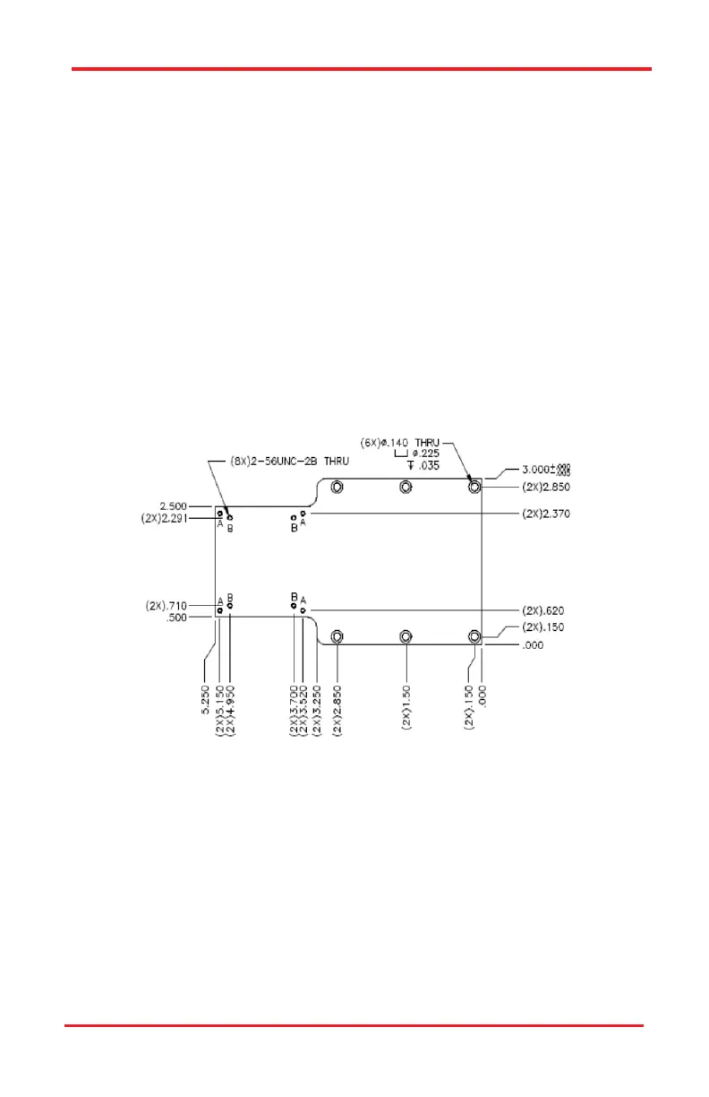
5.5. Mounting a Headstage and Pipette
The PCS-6000 comes with an adapter plate for mounting typical patch-clamp
recording headstages. The adapter plate includes tapped holes to attach dir-
ectly to the plate supplied with the AXON CV-5 and CV-203B headstages; in
addition to holes for use with the HEKA EPC-9 headstage. Additional holes may
be added for other headstages.
1. Make sure the mating surfaces are clean and free of debris.
2. Attach the headstage using four 2-56 x 3/8 screws (two extra screws are
provided). Use the A holes for the HEKA EPC-9 headstages; use the B
holes for AXON headstages.
3. Use the 5/64 hex wrench to tighten the screws.
Figure 5–4 Headstage Adapter Plate
PCS-6000 Series Motorized Patch-Clamp Micromanipulator Chapter 5: Installation

 Loading...


