Rev B, January 10, 2020 Page 5
3.2. Configurations
The PCS-6000 is a modular system. Different configurations are available for
the linear stages. Stages normally are configured with a motor and either 150 or
300 µm piezos. Alternatives to the normal configurations are those that have
coarse motion provided by a manual adjusting screw or no coarse motion at all.
It is possible to get coarse motion only with no fine piezo motion.
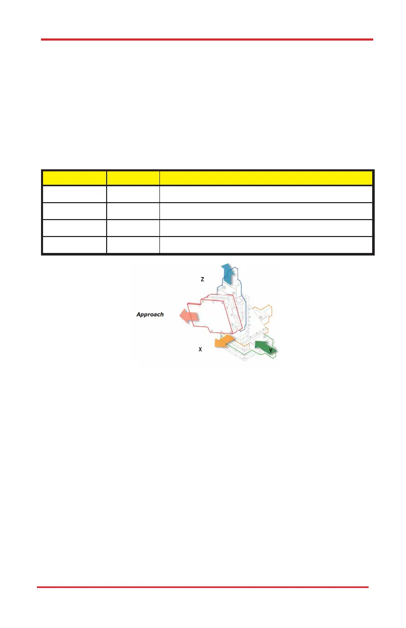
3.2.1. Axes of Motion
The four axes correspond to the following motions:
Axis Number
Axis Name Motion Type
1 X Front to back from operator's perspective
2 Y Left and right from operator's perspective
3 Z Vertical (up and down)
4 Approach Angled (adjustable) axis that the headstage attaches to
Figure 3–2 Graphic Representation of Axes
3.2.2. Right and Left Configurations
A right-hand configuration is used when the manipulator is placed on the right of
the microscope. The manipulator is assembled such that the approach axis pro-
jects to the left and the rotary stage locking knobs are conveniently located on
the outboard (right) side of the manipulator. The left-hand configuration is essen-
tially a mirror image of the right hand.
3.2.3. Manipulator Configurations
PCS-6100
This configuration has three orthogonal axes:
● Axis 1: Front to back
● Axis 2: Left to right
● Axis 3: Vertical
PCS-6000 Series Motorized Patch-Clamp Micromanipulator Chapter 3: Description

 Loading...


