Rev B, January 10, 2020 Page 27
7.1.4. Replacing the Fuse(s)
The unit is supplied with a dual line fuse holder. In the unlikely event the main
power line fuse(s) has blown, it can be replaced. The fact that the main fuse may
have been blown is evidenced by the lack of any indicator lights on the front of
the control unit. (A failed internal power supply may cause similar symptoms but
there is no field fix possible for that condition.)
To replace the fuse(s):
1. Turn off the unit and disconnect from the power source.
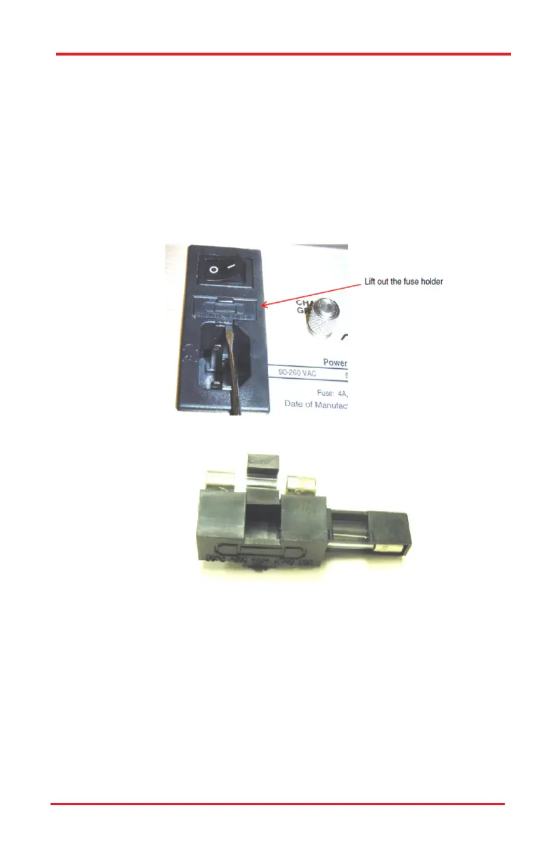
2. Remove the fuse holder by prying up as shown in Figure 7-11.
Figure 7–11 Removing the Fuse Holder
Figure 7–12 Removing and Replacing the Fuse
3. Be sure to replace fuse(s) with the same rating: T-type 4.0A, 250V.
7.2. Adjusting the Friction of the ACU Knobs
To adjust the friction of the control knobs on the ACU, follow the steps bellow:
1. Place the ACU on a flat, stable surface with the control knob you want to
adjust facing up as shown in Figure 7-13.
2. Loosen the two lock screws on the control knob.
3. Press down on the control knob until the desired friction level is
obtained.
PCS-6000 Series Motorized Patch-Clamp Micromanipulator Chapter 7: Maintenance

 Loading...


