Rev B, January 10, 2020 Page 3
2.2. Major Components
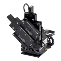
2.2.1. Micromanipulator Assembly
The micromanipulator assembly consists of up to four linear stages and
two rotary pivot stages assembled with a 90° bracket. Depending on the
configuration, the linear stages can have no piezo, a 150 μm piezo or a
300 μm piezo, no long-travel adjustment mechanism, a manual long
travel adjustment screw or a motor.
2.2.2. Axis Control Unit
The Axis Control Unit (ACU) is a rectangular box with large rotary knobs
that control the position of the piezo actuators. Normally, it is placed next
to the microscope.
2.2.3. Joystick
The joystick controls the speed and direction of the servo motors. The
joystick assembly also includes switches to activate specific functions.
2.2.4. Control Unit
The control unit contains the electronics that drive the piezo and the
servo motors.
PCS-6000 Series Motorized Patch-Clamp Micromanipulator Chapter 2: Introduction

 Loading...