66
DMC3S - Manual - 08 - 2021
The operating mode can be selected in the menu Set \ Protections \ Ground directional overcurrent
- 67N \ Common configurations, by setting Mode67N; the available values are I (modulus mode)
and I*cos (projection mode).
For both operating modes, the polarising parameter used as a reference in measuring the phase shift
of the residual current can be selected from the following two options:
• Direct residual voltage, in which the protection uses the residual voltage U
E
phasor measured
directly at the residual voltage input.
• Calculated residual voltage, in which the protection uses the residual voltage U
EC
phasor whose
modulus and argument are calculated as the fundamental component and phase respectively of
the sum of the instantaneous values of the three phase voltages measured at the voltmetric phase
inputs.
It follows that for both of the above detection criteria, the protection measures the phase shift of the
residual current I
E
phasor relative to the residual current phasor (U
E
con for “direct residual voltage”
or U
EC
for “calculated residual voltage”), positive when the current is delayed relative to the voltage
(Φ
E
=(∠U
E
- ∠I
E
, Φ
EC
=(∠U
EC
- ∠I
E
, where ∠ is the argument operator).
The type of residual voltage measurement can be set in the menu Set \ Configuration parameters
A(or B) \ Ground directional overcurrent - 67N \ Common configurations, parameter 3Votype67N;
the available settings are UE (direct) and UEC (calculated).
When set to UE (direct measurement), the thresholds are expressed in p.u. U
En
; when set to UEC
(calculated voltage) the thresholds are expressed in p.u. U
ECn
.
For each of the thresholds I
ED
>, I
ED
>>
a
, I
ED
>>
b
, I
ED
>>> and I
ED
S
b
the characteristic angle can be
regulated relative to the polarising parameter, conventionally positive in the clockwise direction. The
characteristic angle can be regulated in the range 0…359°. The regulation of the characteristic an-
gle identifies the angular position of the characteristic half-axis, which represents the bisector of the
angular trip sector. In an electrical system with isolated neutral, a 90° regulation of the character-
istic angle corresponds to a directionality of the protection “towards line”, while 270° corresponds
to “towards bar”.
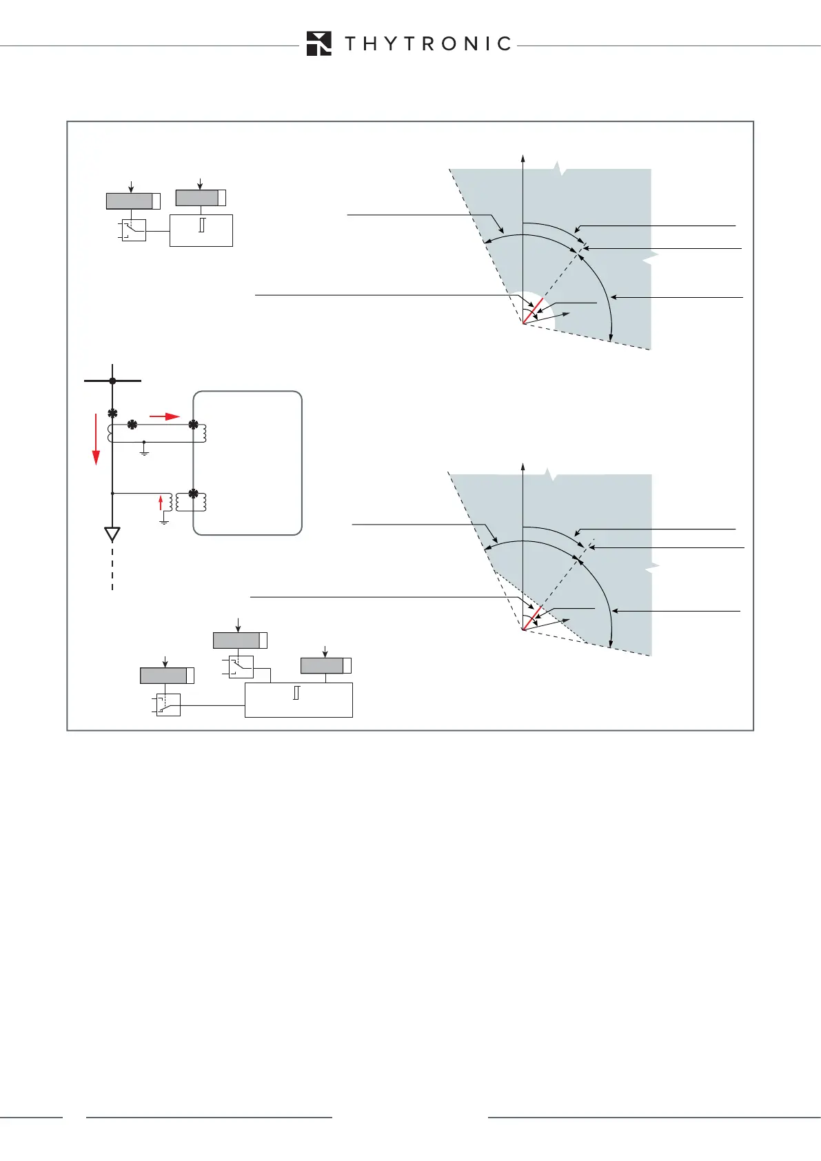
char-F67N-mode.ai
Vectorial diagram of the directional ground protection - 67N
operating mode I (modulus)
Vectorial diagram of the directional ground protection - 67N
operating mode I-cos (projection)
IE
Non-trip sector
(direction towards bar)
Non-trip sector
(direction towards bar)
UE
UEC
Characteristic semi-axis
ΦΕ ορ ΦΕΧ
IED threshold:
(IED>, IED>>a, IED>>b, IED>>>, 67NSb)
(M∙IED>, M∙IED>>a, M∙IED>>b, M∙IED>>>, M∙67NSb)
IE
ΦΕ ορ ΦΕΧ
Characteristic angle
Characteristic angle
UE
UEC
Characteristic semi-axis
IE ≥ IED threshold
IED threshold
IE
I
I∙cos
Mode67N
IE∙COS(ϑE-ΦE) ≥ IED threshold
IED threshold
IE
I
I∙cos
Mode67N
ΦΕ ορ ΦΕΧ
UE
UEC
3Votype67N
BUS
IE
UE
RESIDUAL
VOLTAGE INPUT
RESIDUAL
CURRENT INPUTS
Trip sector
(direction towards line)
Trip sector
(direction towards line)
Angular trip sector
semi-amplitude
Angular trip sector
semi-amplitude
Angular trip sector
semi-amplitude
Angular trip sector
semi-amplitude
LINE
IED threshold:
(IED>, IED>>a, IED>>b, IED>>>, 67NSb)
(M∙IED>, M∙IED>>a, M∙IED>>b, M∙IED>>>, M∙67NSb)