86
DMC3S - Manual - 08 - 2021
— Synchrocheck relay (Synchro check) - 25
Preface
The synchro check function checks that the connection between two grids (synchronous or asyn-
chronous) can be made without risking the stability of the power system.
A typical application is the synchronisation of two bars by means of a coupler.
Measurement inputs
The grid voltages measured at the inputs are used:
• V
1
: the reference measurement: the parameter Voltage measurement for synchro check
in the menu Set \ Base selects the parameter (phase voltage U
L1
, U
L2
U
L3
)
[1]
.
• V
2
voltage measurement (phase-ground) to be synchronised. The input otherwise used to measure
the residual voltage is used (clamps MV5-MV6); the selection uses the parameter Measurement
UE or V2 in the menu Set \ Base.
[1]
Output relays
The synchro check function can activate one or more output relays according to the usual matrix
assignment criterion.
You must select Pulse mode (menu Set \ Relay) and program the duration according to the specifi-
cations of the breaker.
The devices uses the measured difference in frequency between the two grids to determine whether
the grids are synchronous or asynchronous.
Synchronous grids
For synchronous grids the final relay is commanded (synchronisation ok) when the following con-
ditions obtain:
• the trip signal (keypad, logical input or communication) is active,
• the block input signal (keypad, logical input or communication) is inactive,
• the breaker is open,
• the control of inputs V
1
and V
2
(function 74VT) is ok,
• the two measured frequencies are in the permitted operating range (f
n
± f
RANGE
) for an adjustable
time of no less than t
STAB
,
• the difference, which defines the synchronous grid condition, between the two measured frequen-
cies is less than an adjustable threshold (df
-GRID
) for an adjustable time of no less than t
STAB
,
• the value of the two voltages is between a minimum threshold (V
min-SYNC
) and a maximum thresh-
old (V
max-SYNC
), both adjustable, for an adjustable time of no less than t
STAB
,
• the difference between the voltages V
1
and V
2
(with V
1
> V
2
) is less than an adjustable threshold
(dV12
-SYNC
), or the difference between V
2
and V
1
(with V
1
< V
2
) is less than an adjustable thresh-
old (dV21
-SYNC
), for an adjustable time no less than t
STAB
,
• the phase shift between V
1
and V
2
(with V
2
delayed relative to V
1
) is less than an adjustable thresh-
old (dp12
-SYNC
), or that between V
1
and V
2
(with V
1
delayed relative to V
2
) is less than an adjusta-
ble threshold (dp21
-SYNC
), for an adjustable time no less than t
STAB
,
• the above conditions persist for a time no less than the adjustable parameter (t
SYNC
).
If any of the above conditions does not obtain, the close command is not issued.
Note 1 This parameter can only be modified at Level 1
BUSBAR 1
BUSBAR 2
25
Close command
DMC3
V
2
V
1
Synchronisation of two bars
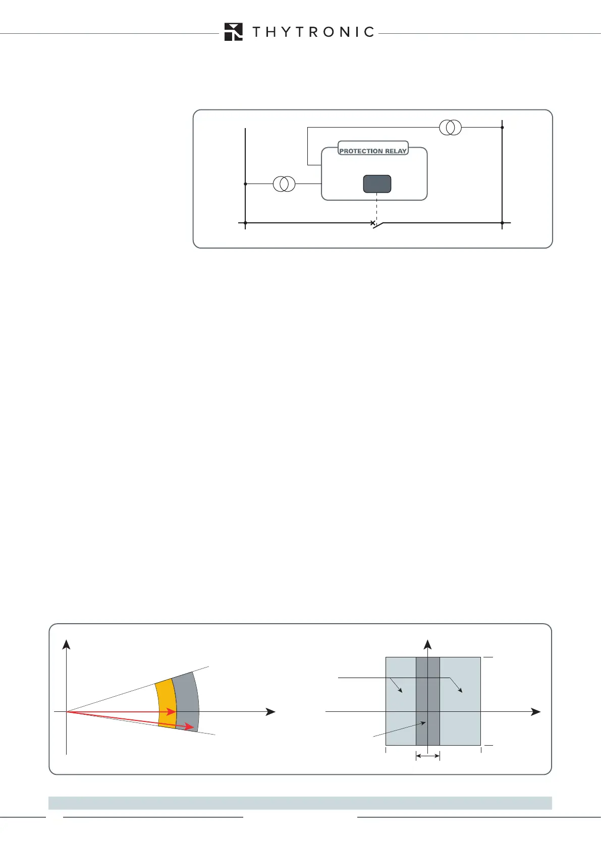
Regulation ranges for the synchronisation check function (25)
dv12-SYNC
dv21-SYNC
dp12-SYNC
(V2 delayed relative to V1)
dp21-SYNC
(V2 in advance of V1)
{
{
V2
V1
V
Asynchronous grids
Synchronous grids
f
df-GRID
dv21-SYNC
(V2>V1)
df21-SYNC
(f1<f2)
dv12-SYNC
(V1>V2)
df12-SYNC
(f1>f2)