78
DMC3S - Manual - 08 - 2021
— Breaker monitoring
Preface
A variety of diagnostic, measurement and control functions are provided:
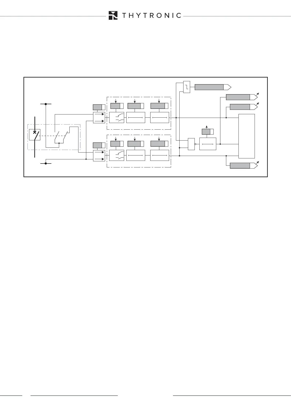
• The relay determines the position of the breaker by monitoring the status of auxiliary contacts 52a
and 52b. This information enables the user to issue the open/close commands in complete safety.
• An approximate threshold for the wear of the breaker's poles can be set; when the sum of the in-
terrupted currents (SI or SI
2
) or the number of opening commands violates this threshold, an alarm
signal is issued. This function enables the user to schedule maintenance.
• The relay determines the opening time by monitoring the status of auxiliary contacts 52a and 52b; if
it is too high, an alarm signal is issued.
Operating logic
By convention, the status of auxiliary contact 52a corresponds to the position of the breaker (52a
open = breaker open), while that of 52b is opposite to the position of the breaker (52b open = breaker
closed); the two auxiliary contacts must be mapped to two logical inputs.
To do so, the functions 52a and 52b must be configured in the menu Set \ Input board inputs \ Input
IN1-1...(Input IN1-6).
The said logical inputs must be programmed with Direct logic and the activation/deactivation timers
IN1 tON, INx tON, IN1 tOFF and INx tOFF must be zeroed and set to DIRECT operating
logic.
BREAKER CONTROL
Two output relays can be programmed to open and close the breaker; to do so, set the parameters
CBopen-K and CBclose-K in the menu Set \ Breaker monitoring \ Associated relays-LEDs; the
position of the breaker can be displayed by assigning the status to two LEDs (parameters CBopen-L
and CBclosed-L).
All parameters are common to the two calibration configurations.
OPENING COMMAND BREAKER DIAGNOSTICS
The breaker diagnostic function uses a variety of criteria to estimate the wear of the breaker.
1) Opening command count (ModeN.Open ON). When the set threshold is violated (N.Open) an
alarm signal is issued, which can be assigned to a final relay and/or indicator LED.
2) Opening load command count (ModeN.MnvLoad ON). When the set threshold is violated
(N.MnvLoad) an alarm signal is issued, which can be assigned to a final relay and/or indicator
LED.
3) Opening no load command count (ModeN.MnvNoLoad ON). When the set threshold is vio-
lated (N.MnvNoLoad) an alarm signal is issued, which can be assigned to a final relay and/or
indicator LED.
4) Sum of interrupted currents at each pole (ModeSumI ON). When the set threshold is violated
(SumI) an alarm signal is issued, which can be assigned to a final relay and/or indicator LED..
5) I
2
t sum of interrupted currents at each pole (ModeSumI ON). The protection calculates the sum
of the specific pass-through energy I
2
t on the basis of the measurement of the phase currents at
the time of the open command, and using the user programmable breaker opening time specifical-
ly provided for calculating I
2
t (tbreak). When the set threshold is violated (SumI^2t) an alarm
signal is issued, which can be assigned to a final relay and/or indicator LED..
6) Duration of open command (Mode-tOpen ON). The protection measures the time between
the trip command of a protection function, selected in relation to the associated final relay
(Ktrig-break), and acquisition of the breaker open status. When the set time period is exceeded
(tbreak>) an alarm signal is issued, which can be assigned to a final relay and/or indicator LED..
Fun-CB-position.ai
Towards CB diagnostic
TRIPPING MATRIX
(LED)
52a ON/OFF
t
break
0T
t
break
CB monitoring
Opening transition
52b ON/OFF
52a
52
52b
+UAUX
-UAUX
52a
52b
Binary input INx
T 0
INx
t
ON
T0
n.o.
n.c.
INx tON
Logic
INx tOFF
INx
t
OFF
Binary input INx
T 0
INx
t
ON
T0
n.o.
n.c.
INx tON
Logic
INx tOFF
INx
t
OFF
=1
Functional diagram of the breaker position monitoring function