74
DMC3S - Manual - 08 - 2021
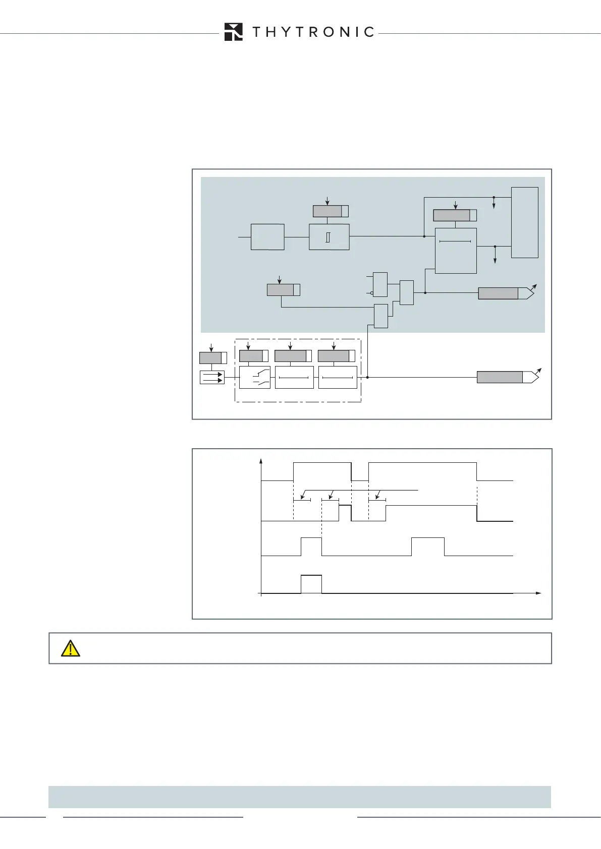
— Logical block - Block1
To block the trip of a given protection function, one can map to the logical block function to the
logical inputs.
[1]
The logical inputs are mapped in the menu Set \ Input board inputs \ Input IN1-1 (Input IN1-6); select
Logical block for the parameter Input function IN1-x (x=1...6)
All protection functions for which the logical block is enabled are blocked when the signal is active.
The status of the function's logical block is available in read (ThySetter and comms interfaces); it is
active when the following conditions obtain simultaneously:
• Logical input activated,
• Start of function active (ON),
• Trip of function in standby (OFF).
The logical block is not subject to inhibition criteria after a programmable delay, hence the associat-
ed protection function is block for as long as the input remains active.
[2]
Note 1 In this description, the logical block is called both “Logical block” and “Block1” without distinction
Note 2 The block signal holds the timer in reset
Blocco_L.ai
RESET
Operate time
0T
Measure
Input
TRIPPING MATRIX
(LED+RELAYS)
BLK1xx
Operate time
Threshold
Startxx
Startxx
Tripxx
Tripxx
&
&
Enable (ON≡ Enable)
Block1 input (ON≡ Block)
Block1 info (internal state)
xxBLK1
Block1
Block1
Binary input IN1-x (x=1...6)
T 0
Logic
IN1-x
t
ON
IN1-x
t
ON
IN1-x
t
OFF
T0
n.o.
n.c.
IN1-x
t
OFF
&
Protection threshold xx enabled to receive logical block
Functional diagram of logical block - Block1
Start
Block1 (input)
Block1 (output)
Trip
Operate time
t
Timers-Block1.ai
Logical block timers (Block1)
CAUTION
The activation of a logical input to which the logical block has been mapped blocks all protections
for which the block is enabled