82
DMC3S - Manual - 08 - 2021
— CT Monitoring - 74CT
Preface
The function detects interruptions of the secondary phase CT circuits and/or DMC3S panel input cir-
cuits by measuring the symmetry of the secondary CT currents themselves. The symmetry is meas-
ured in terms of the ratio between the minimum and maximum RMS values of the three fundamental
components of the three phase currents (I
LMIN
/I
LMAX
).
The function starts if both the following conditions are satisfied:
• (I
LMIN
/I
LMAX
) < S<
• I
LMAX
> I*
where S< is the trip threshold and I* is the maximum threshold of the three phase currents, both of
which can be set by the user.
When the function starts, so does the count of timer t
S
<. If the two above conditions persist, when
the operating time expires, the function trips (Trip), otherwise it is reset. The trip characteristic is
definite time.
When the function is actuated, the associated final relay S<TR-K and/or LED S<TR-L is trig-
gered.
The function can be enabled or disabled (ON/OFF).
When a fault is detected, the CT monitoring function activates the 59N emergency function (59N
eme), blocks functions 32P, 50/51, 67 and 67N) and, after a configurable delay t
VT-AL
, issues an alarm.
If the parameter S<-BLK1 is set to ON and a logical input is set to acquire the logical block
(Block1), the function is blocked for the activation time of the logical input in question. The operating
timer is held in reset mode so that the operating time count starts when the block signal expires;
[1]
the
logical block function can be assigned to the input in the menu Set \ Input board inputs \ Input IN1-1...
(Input IN1-6).
All parameters are available in the menu Set \ CT -74CT monitoring
Notes 1 For a detailed description of the operation of the logical block (Block 1) refer to the paragraph “Logical block” in the chapter MONITORING AND
CONTROL. .
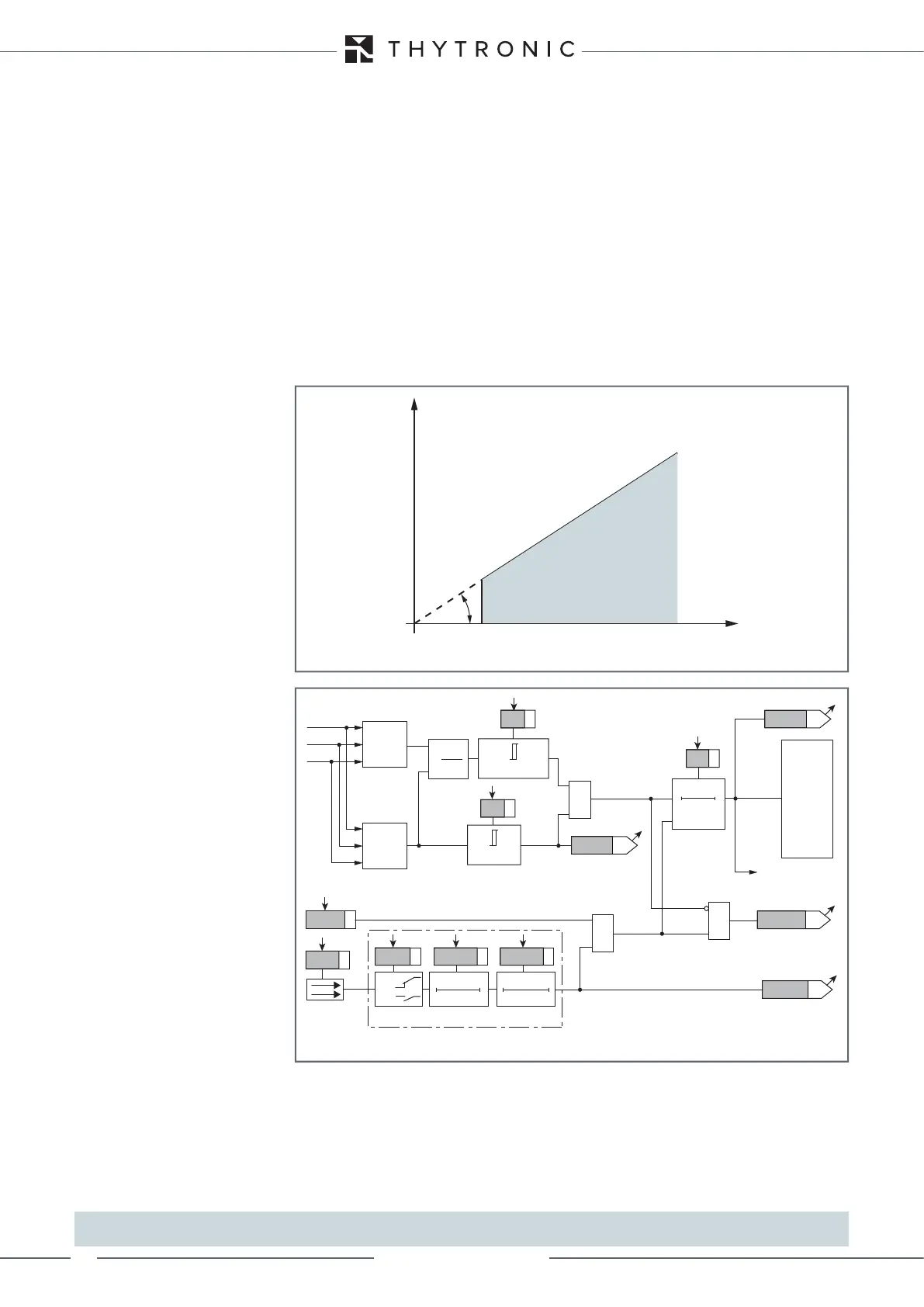
char74CT.ai
I*
α
ILMIN
ILMAX
tga=S<
Phase CT monitoring function trip characteristic -74CT
TRIP
NO TRIP
Fun-74CT.ai
Functional diagram of the phase CT monitoring function - 74CT
&
0
T
ts<
tS<
ILMIN/ILMAX< S<
S<
TRIPPING MATRIX
(LED+RELAYS)
Trip S<
Start I*
BLK1 S<
ILMAX >I*
I*
Enable (ONEnable)
Block1 input (ONBlock)
&
&
S<BLK1
Block1
Block1
Binary input INx
T 0
Logic
INx tON
INx tON INx tOFF
T0
n.o.
n.c.
INx tOFF
IL1
ILMAX
IL2
IL3
ILMIN
ILMIN
ILMAX
S<TR-K
S<TR-L
RESET
ACTIVATES 59N(Eme)
BLOCKS 32P/51/67/67N