Rev E TR-220 90 008 088-1
2-38
12. The operator may now observe the AUT TCAS display to ensure correct
operation. Once the simulated intruder’s range has reached 0 nmi, the Test Set
will reverse the heading and return back to the start point. This will continue,
back and forth, until the operator stops the simulation.
13. At any point during the simulation, the operator may STOP the intruder at any
range. Toggle the TO/START-FROM/STOP switch twice to the STOP position.
The intruder will stop and hold at that range. The operator now may move the
Test Set to a different location around the AUT to check that correct azimuth
information is being displayed on the TCAS display.
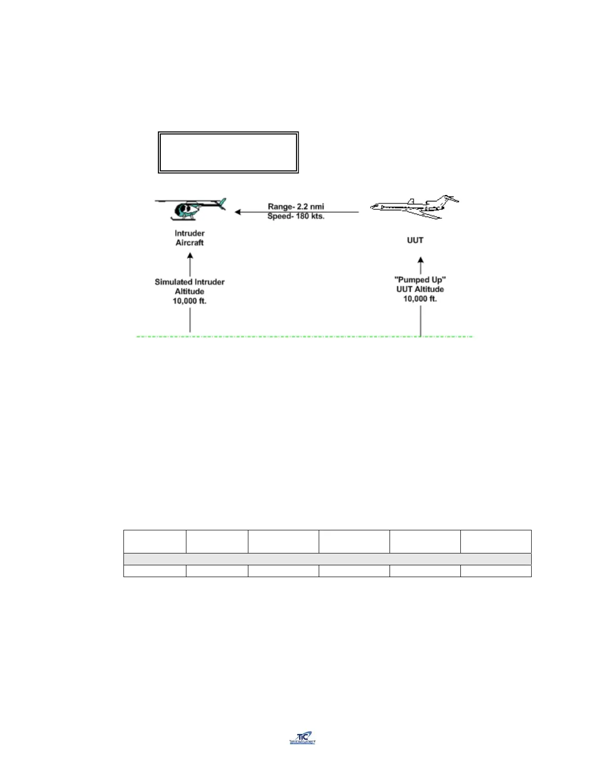
14. By selecting a starting altitude above or below the “Pumped UP” UUT altitude,
the operator can simulate an intruder converging on the UUT from above or
below the UUT. Table 2-5 lists several scenarios, which can be utilized for this
purpose.
14a. For Example: Select Scenario #10.
Scenario
#
UUT
Altitude
Starting
Altitude
Velocity
TCAS
Distance
Vertical
Speed
10 15000 ft. 30,000 ft. 600 kts 30 nmi -5000 fpm
14b. Enter the values above in the TCAS Scenario Setup menus (Paragraph
2.15.2) and “Pump Up” the UUT aircraft to 15000 ft.
14c. Start the Intruder simulation as described in Paragraph 2.15.5.(11)
TRK 180Kts 10000’ /
2.2 nm +000fpm FRM