Tinius Olsen MP1200 Extrusion Plastometer Page 18-2
Operation Manual # 02002215
18.1.2.1 Normal Operation
There are three options for PPDT type that are programmed in the Calibration
Mode: type 0 (none), type 1 (encoder without index pulse) and type 2 (encoder with
index pulse). Select type 2 for the PPDT.
The PPDT is mechanically and electrically structured so that the index pulse will
trigger just as the arm starts to move down from its upper-most (resting) position.
The relationship between the index pulse and the horizontal position are established
during the calibration process. By detecting the index pulse and knowing the
horizontal position (defined under calibration), the controller knows the position of
the tip (height of piston) at any time.
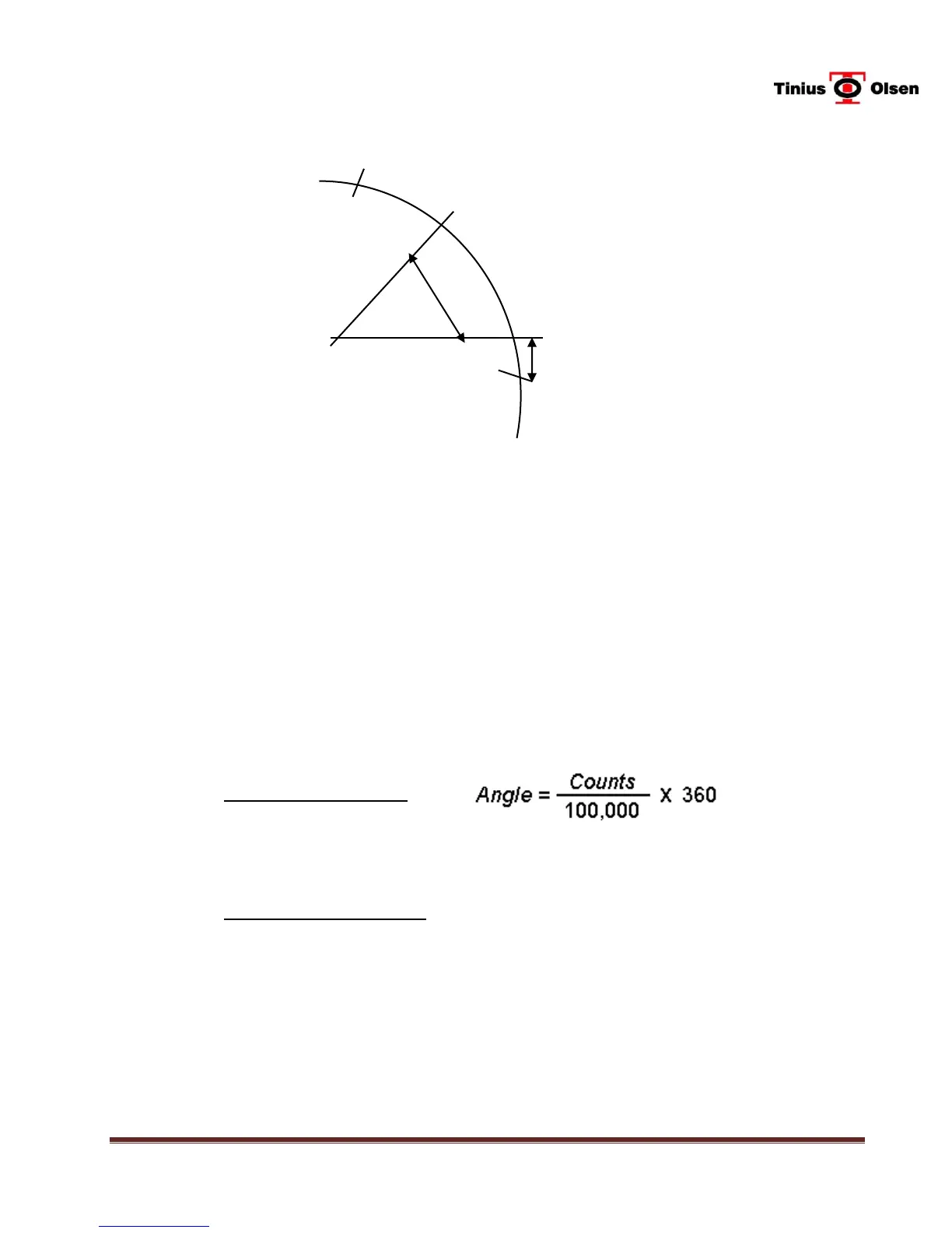
The angle, relative to horizontal (0 degrees), is as follows.
PPDT Angle Calculation
Where counts is the number of encoder counts.
The distance of the piston above the orifice is calculated as follows.
Piston Position Calculation
Position = Offset + (ArmLength * sin (Angle))
Where the Offset and ArmLength are defined in the Calibration Mode and Angle is
defined in the equation above. The Arm Length multiplied by the sine of the angle
(relative to the horizontal) gives the linear position (relative to the horizontal). The
Offset is added in to give the height above the top of the orifice (Piston Height).
Horizontal Reference Position
 Loading...