TMQ AP9 Autopilot (V6.0 - 965) Page 18 of 51 31/1/2017
Interconnection:-
If your autopilot is to be connected to other navigational equipment using a cable not
supplied by TMQ, a suppression ferrite MUST always be fitted to the cable close to the
TMQ unit.
List of Components
The AP9 autopilot control system when packed has the following components:
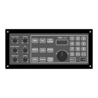
· AP9 Main Control Panel – 2 metre power cable
· Compass, Compass Top Sensor or Electronic Compass (depending on model
ordered) – 5m cable attached
· Rudder Feedback Unit – Heavy Duty (RFUH) or Standard (RFUS)
· Rudder feedback cable – 14 metre 3 core.
· Rudder Linkage assembly
· Owners manual, RFU mounting bracket, mounting screws
BEFORE INSTALLATION, ENSURE YOU HAVE PURCHASED THE
CORRECT PARTS FOR YOUR VESSEL.
TMQ Autopilots are intended for use in three (3) basic configurations:
1. AP9 can be used to control most brands of solenoid control valves (hydraulic).
System components required:
· Control unit
· Compass
· Rudder feedback unit
2. AP9 and mechanical drive system - used to drive most hand-operated mechanical
steering systems eg: rod & chain, push-pull or pull-pull systems. Some helm
pumps can also be used with a mechanical drive to provide an installation, which
requires no additional hydraulic pump. System components required:
· Control unit
· Compass
· Rudder feedback unit
· Mechanical drive
3. AP9 and reversing hydraulic pump - used with hydraulic steering systems.
Different pump units are used to cater for a wide range of systems. Correct
installation is required and pump size and voltage should be considered BEFORE
installing the hydraulic pump. System components required:
· Control unit
· Compass