Do you have a question about the TMQ AP9 and is the answer not in the manual?
Automatic pilots are navigational aids; constant watch is required.
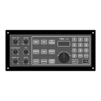
Hybrid digital/analogue autopilot with various interfaces and controls.
Displays current heading; autopilot applies no steering control.
Maintains selected magnetic course using keypad, knob, or remote.
Control rudder via knob or steer along GPS track.
Watch and commercial watch timers with alarm functions.
Procedures for entering and exiting auto steering mode.
Adjust course using control knob or arrow buttons.
Details on engaging Power Steer and GPS modes.
Press GPS button to engage GPS steering mode.
Ensure GPS outputs NMEA 0183 data and has a route programmed.
Set, reset, or disable standard and commercial watch timers.
Sets vessel's rate of turn to prevent sharp turns.
Adjusts heading sensitivity for steering accuracy in varying conditions.
Applies counter rudder to stop vessel swing beyond desired course.
Adjust trim control in POWER STEER to make the ship steer straight.
Limits rudder travel to prevent damage to steering gear or drive system.
Determines rudder angle applied for steering responsiveness.
Control AP9 with hand remote or steering lever.
Engage auto and power steer modes using the hand remote unit.
Engage steering lever or electric helm for follow-up steering control.
Ensure proper installation to avoid electromagnetic interference and ensure performance.
Keep cables away from radio sources; ensure correct parts are purchased.
Lists the components included in the AP9 autopilot control system package.
Use suppression ferrite; route cables away from radio sources.
Install fluxgate compass in a position free of magnetic influence.
Mount electronic compass away from magnetic interference.
Connect compass cable wires to the AP9 internal connection strip.
Mount electronic compass horizontally with arrow pointing towards the boat's bow.
Ensure unit is not immersed in water; select position adjacent to tiller arm.
Check arm movement; verify RFUS/RFUH switch selection.
Mount remote bracket, connect cable; cut hole for lever, secure, connect.
Calibrate remotes using STANDBY mode, keypad, and buttons.
Details pin configuration for NMEA connections on terminal strip T6.
AP9 accepts NMEA 0183 GPS data for waypoint or heading reference.
Connect GPS/C-Plot data plugs for waypoint steering.
Connect TMQ second station display to T5 Remotes and T6 NMEA.
Manage heading data input from NMEA sources and output.
Wiring for compass; AP9 prioritizes NMEA heading data.
Mount siren, route wires, connect siren leads to T4 Ext Al terminals.
Considerations for mechanical drives, hydraulic pumps, and solenoid valves.
Ensure tight connections; use isolating switch and protection circuit for pumps.
Verify voltage, polarity, connections, cables, and mechanical parts.
Test standby, rudder limits, heading alignment, and auto mode.
Check rudder lock-to-lock time is approx. 15 seconds for good course holding.
Sail to calm water, switch on AP9, check compass headings.
Set initial controls (Rate of Turn, Weather, Trim) before trials.
Perform further trials on ancillary equipment like remotes, GPS inputs.
Limits prevent rudder over-travel; factory set to approx. 30 degrees.
Procedure to reset rudder limits; ensure limit control is clockwise.
Calibrate compass if inaccurate: select STANDBY, enter 905, hold STANDBY, press GOTO.
Internal settings for different operations and parameter control.
Enter mode number, hold STANDBY, press GOTO, perform operation.
Details configurations for various remote control setups.
Configuration for Remote Mode 6 (similar to Remote 5).
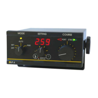
Flush mounted instrument for clear rudder position indication.
Wireless remotes and levers for enhanced control.
Details on electric wheel, hydraulic pumps, and linear drives.
| Brand | TMQ |
|---|---|
| Model | AP9 |
| Category | Autopilot System |
| Language | English |