TMQ AP9 Autopilot (V6.0 - 965) Page 19 of 51 31/1/2017
· Rudder feedback unit
· Reversing hydraulic pump
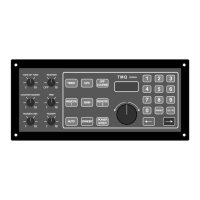
Installation of Main Control Unit
Position & mounting
· Select a dry position
· Provide access for wiring to rear of the pilot (minimum compass, feedback,
power and drive)
· Provide a cut out section in the dash
· Install control unit and fix with four screws
· Route the power cable to 12 or 24 VDC power source
· Check AP9 WEATHER switch is OFF
· Connect power cable to the AP9
Note: To control the autopilot from a remote position, fit a remote unit.
Wiring
· Keep autopilot connection cables away from radio aerials and cables
· Select a drive unit interconnection cable of appropriate current rating to prevent
voltage drop
Compass Installation
There are three types of compass suitable for this autopilot - a TMQ compass-top sensor
(CTSB), a TMQ fluxgate compass (COMMAGB) or TMQ electronic compass
(ELECOM)
Installing a Compass-Top Sensor
A compass top sensor should be used as the pilot heading reference unit for steel boats.
Before attaching the CTSB to the top of a flat top compass, ensure there are no defects in
the compass, eg: sticking card, as this will affect the operation of the autopilot. Also, the
compass should be compensated.
Position
· Firstly determine the correct position of the CTSB on the compass glass top
(CTSB is central on the top and cable facing aft)
· Route the cable to the AP9 control unit position