Installation
Installing GNSS Receivers
2-14
P/N: 1049060-01
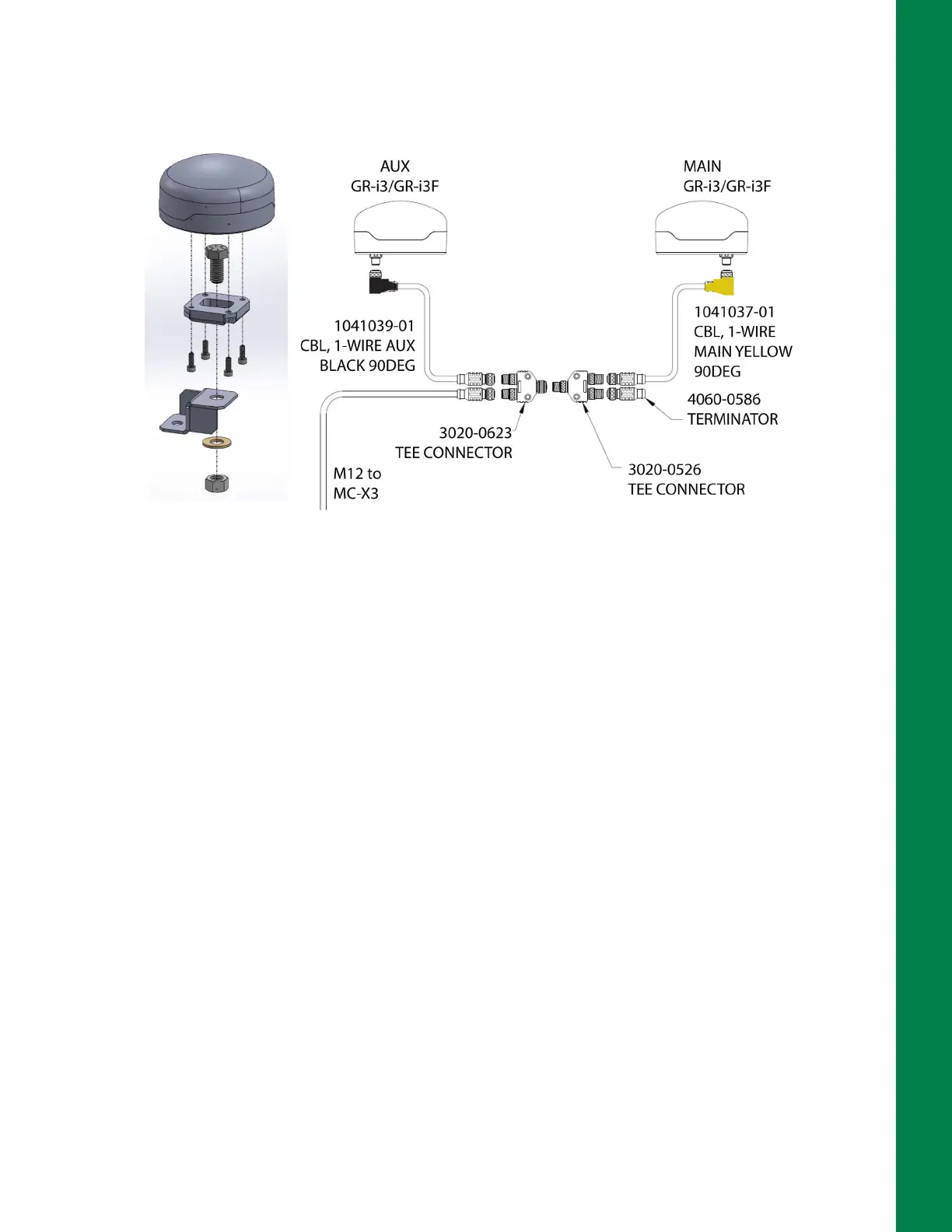
4. Connect the single side of the Tee Connector to the single side of a second Tee Connector
(Figure 2-18 on page 2-14). The connection will be completed in the Auxiliary GNSS Receiver
installation process.
Figure 2-18: AUX GNSS Receiver & M12 Cable Connections
Install Auxiliary GNSS Receiver
The Auxiliary GNSS receiver is secured to the roof at the back of the cab with CAT D6 Bolt-On GPS
Mount MCMAX bracket (P/N 1040166-01).
1. Locate the 1-Wire AUX Black 90 Degree cable (P/N 1041039-01) cable with the black right
angle connector and connect it to the GR-i3/GR-i3F GNSS receiver (Figure 2-18).
2. Assemble the CAT D6 Bolt-On GPS Mount MCMAX bracket and secure the GNSS receiver as
shown in Figure 2-18.
3. Connect the 1-Wire AUX Black 90 Degree cable from the AUX GNSS receiver to the Tee
Connector (P/N 3020-0623) from the Main GNSS receiver (Figure 2-18).
4. Connect an M12 extension cable to the remaining connector on the Tee connector (P/N 3020-
0623). This M12 cable will be routed to the MC-X3 in the cab later in the installation.
5. Use zip ties to secure all cables.