Installation
Completing MC-X3 Connections
2-17
P/N: 1049060-01
Completing MC-X3 Connections
Several cable connections route to and from the MC-X3 Controller (refer to the Caterpillar 3D-
MC
MAX
D5/D6 Dozer System Diagram, Figure 1-2 on page 1-2).
Identify each cable, as labeled on the associated cable jackets. The MC-X3 will connect to a breakout
cable (P/N 1033631-02) with multiple extensions, as well as cellular and radio cables.
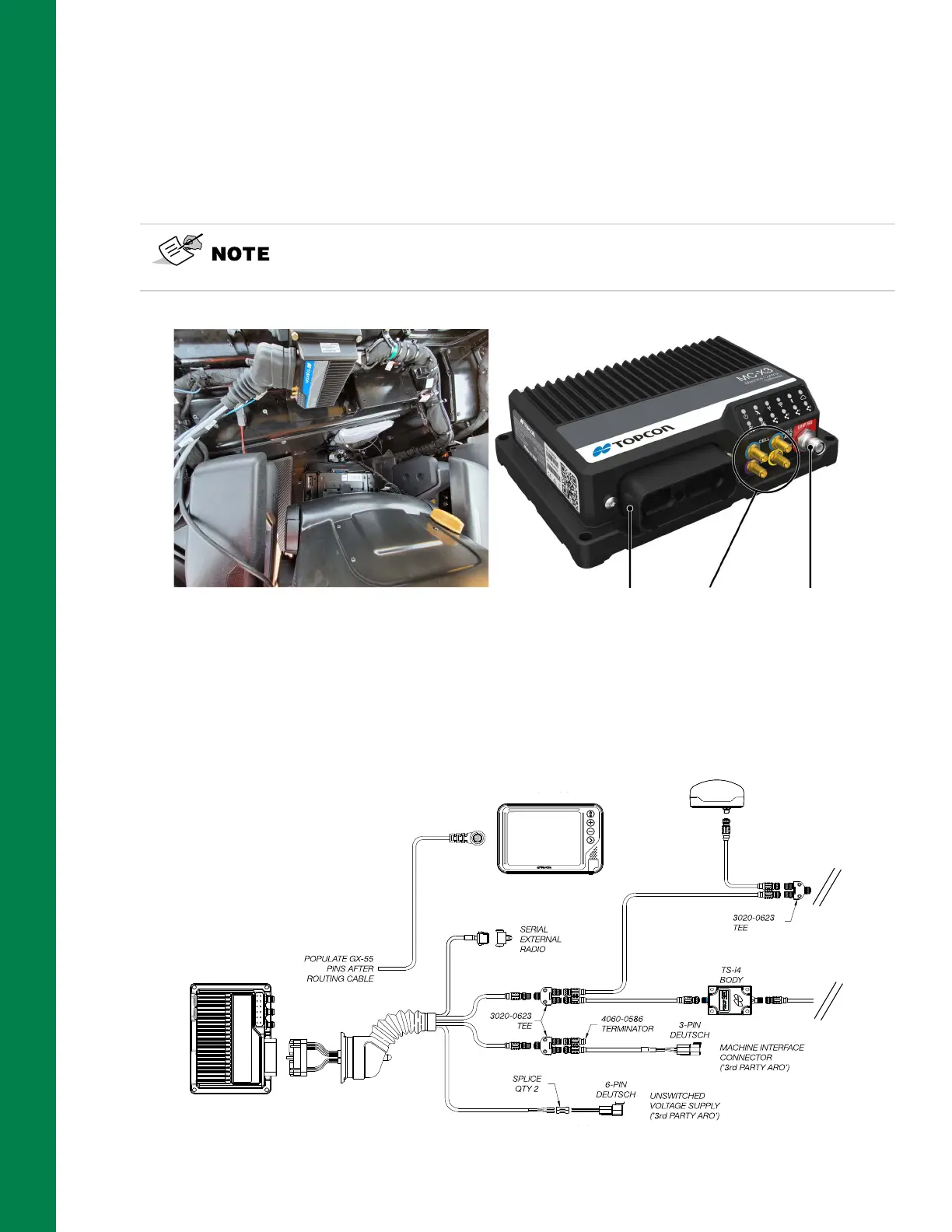
Figure 2-22: MC-X3 Connections
1. Connect the breakout cable (P/N 1033631-02) to the MC-X3 Controller (Figure 2-23).
2. Refer to Figure 2-23 Breakout Cable Connections for the CAN Open bus connections.
Figure 2-23: Breakout Cable Connections
Use the Instructions Card (P/N 1041036-01) attached to the Breakout Cable
Assembly, to identify each cable. Detailed connection information is
included on the Instructions Card.
Breakout Cable Diversity
Antenna
Radio
Antenna
1040764-01
1033631-02
1041039-01
AUX GR-i3/GR-i3F
1040763-01
GX-55
MC-X3