Installation
Installing TS-i4 C-Frame Sensor
2-5
P/N: 1049060-01
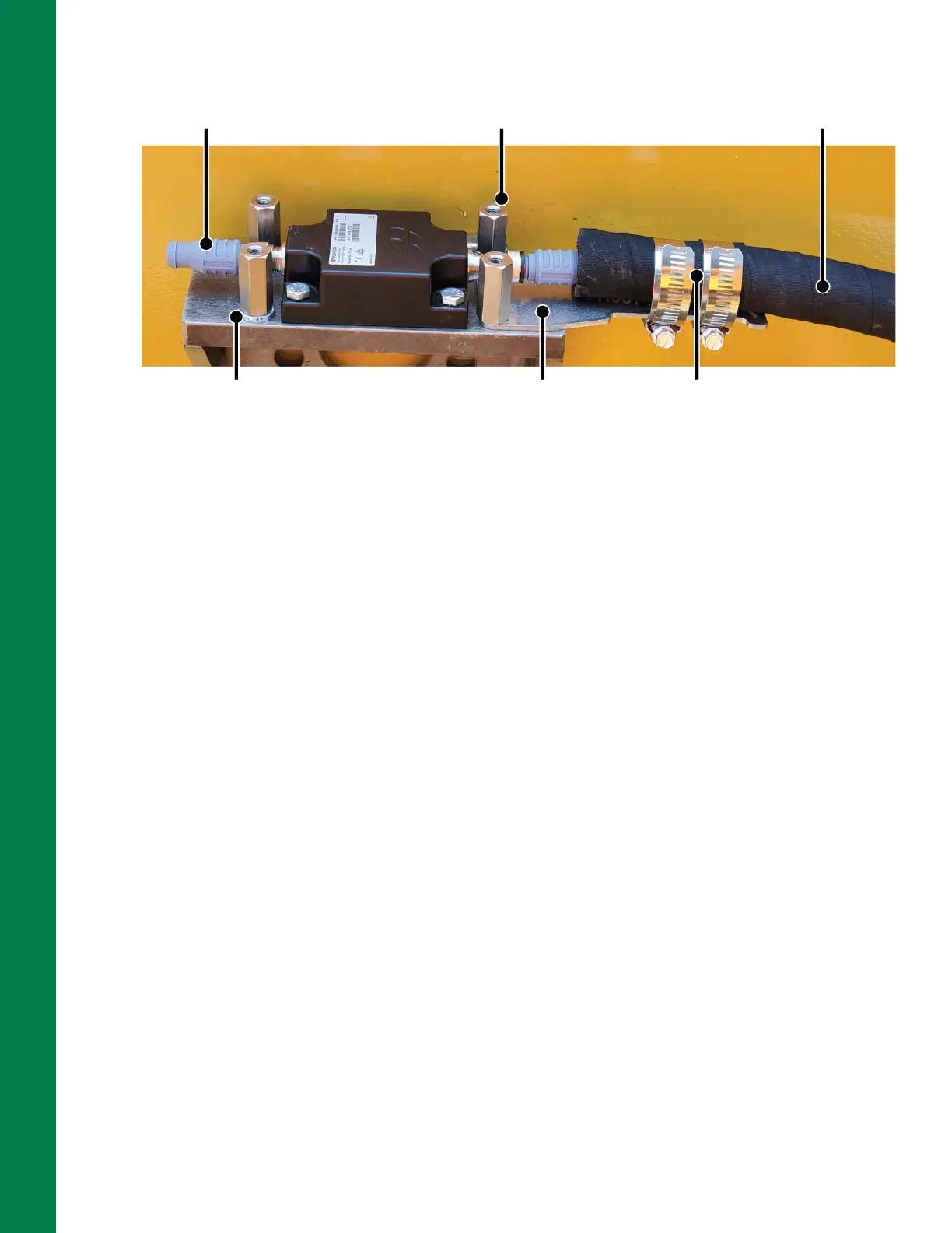
Figure 2-7: Secure and Protect the TS-i4 Blade Sensor
25. Connect the M12 cable to the inside connector of the TS-i4 Blade sensor (Figure 2-7).
26. Use two hose clamps to secure the protected M12 cable in position on strain relief plate
(Figure 2-7).
27. Secure the protected M12 cable in the weld-on hose clamps.
Installing TS-i4 C-Frame Sensor
The TS-i4 C-Frame sensor is mounted on the frame between the TS-i4 Blade sensor and the dozer’s
front grill using the 3rd TS-i4 Add-On Kit (P/N 1043613-01).
Orientations:
• Label Up or with Label Down (Z-axis vertical refer to Figure 2-1 on page 2-1).
• Mounted with connectors (X-axis) either parallel to the dozer blade or parallel to the centerline of
the body (refer to Figure 2-1 on page 2-1).
1. Map out the cable routing, clearance for protective cable cover, and hose clamp locations to
identify a suitable location for the weld plate.
2. Consider the range of movement for the blade, supporting structure, hydraulic cylinders, and
hydraulic hoses when routing cables.
3. Provide adequate clearance for connection to protected M12 cable, strain relief plates, and
cover.
4. Remove any debris in the area where the TS-i4 IMU sensor will be installed.
Standoff
(4 PLCS)
M6 Washer as
Spacer (2 PLCS)
Strain Relief
Plate
M12 Cable Protected
with Hydraulic Hose
Hose Clamps
(2 PLCS)
Terminator