Installation
Installing TS-i4 C-Frame Sensor
2-6
P/N: 1049060-01
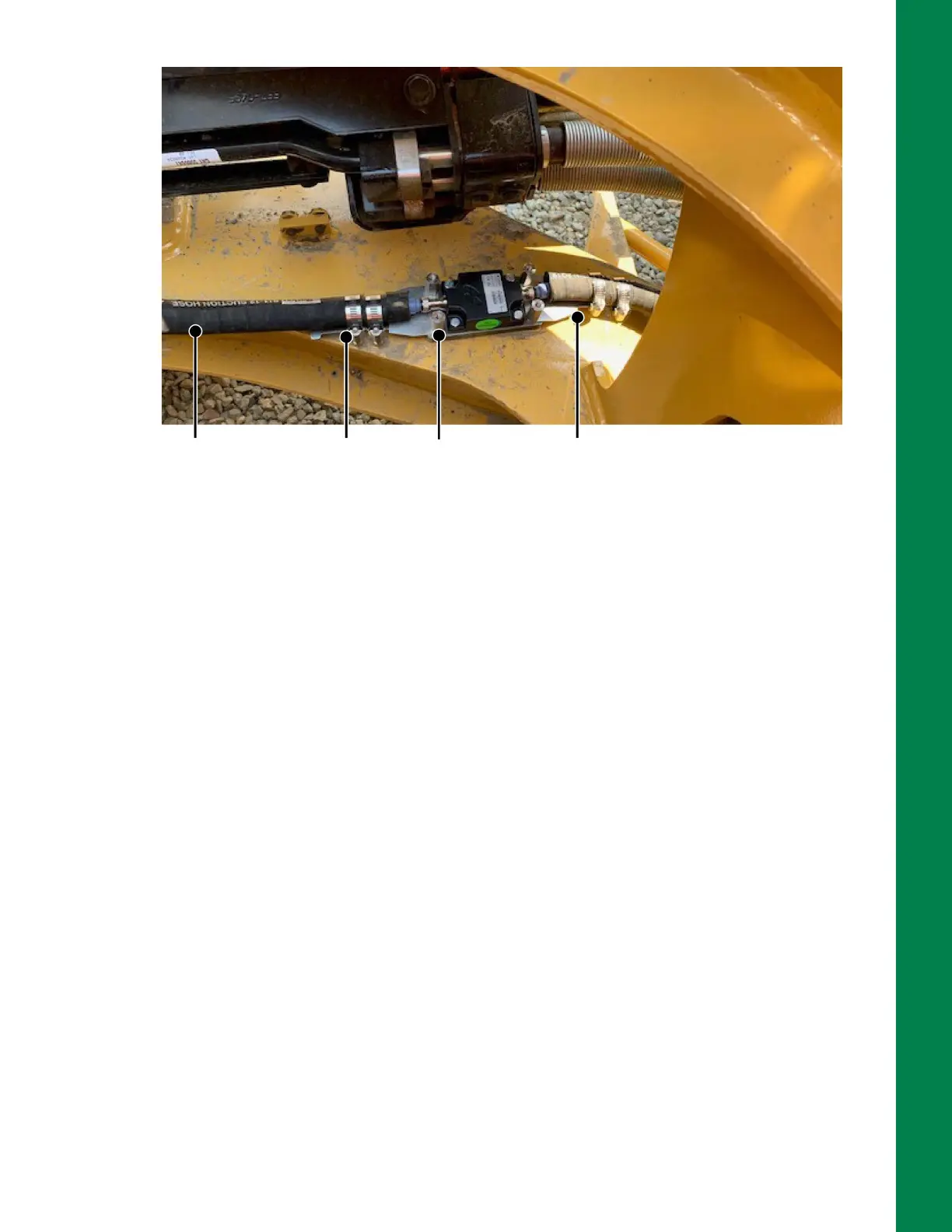
Figure 2-8: TS-i4 Sensor Secured to C-Frame
5. Position the Excavator TS-i4 Guard Weld-On Base plate (P/N 1032189-01) from the 3rd TS-i4
Add On Kit (P/N 1043613-01) either parallel to the dozer blade or parallel to the centerline of the
body (Figure 2-8).
6. Use a permanent marker to outline the weld-on plate location on the C-frame for welding.
7. Prepare the welding area by grinding off the paint around the area where the weld-on plate will
be installed.
8. Position the weld-on plate using clamps or magnets.
9. Weld the weld-on plate to the dozer C-Frame, using a suitable welding method (Wire Welding or
Stick Welding). The weld leg size should be 6 mm (1/4 inch), and weld lengths should be at least
50 mm (2 inches).
10. Remove any weld slag using a slag hammer or other suitable tool. Scrub off the weld with a wire
brush to prepare it for painting.
11. Paint the weld-on plate and welds with rust-preventive paint, in a color that matches the
machine. Keep threaded holes clear of paint.
12. Mount the TS-i4 IMU sensor to the weld-on plate.
13. Use four standoffs to secure two strain relief plates to the weld-on plate (Figure 2-8).
14. Connect the protected M12 cable from the TS-i4 Blade sensor to the TS-i4 C-Frame sensor.
15. Secure the protected M12 cable from TS-i4 Blade sensor to the TS-i4 C-Frame sensor strain
relief plate using two hose clamps (Figure 2-8).
Strain Relief
Plate (2 PLCS)
Standoff
(4 PLCS)
Protected
M12 Cable
Hose Clamp
(4 PLCS)