TS-i4 IMU Sensor Orientation
P/N: 1049060-01
2-1
Installation
TS-i4 IMU Sensor Orientation
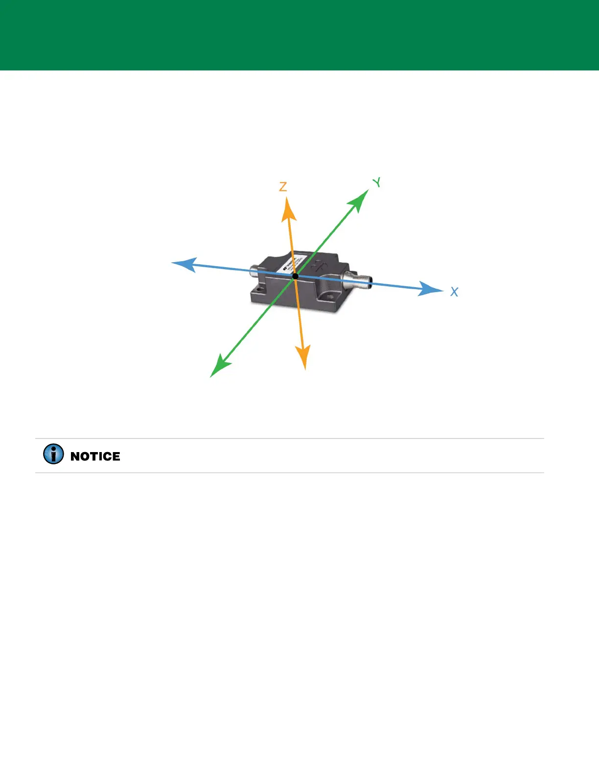
The TS-i4 IMU sensor orientation is described using the X, Y, and Z axes where Z runs up and down,
X runs lengthwise across the sensor and through the connectors, and Y runs across the width or the
edge with no connectors (Figure 2-1).
Figure 2-1: TS-i4 IMU Sensor Orientation
Follow the specific installation instructions for each TS-i4 IMU sensor installation location.
Installing TS-i4 Blade Sensor
The TS-i4 Blade sensor is installed on the back of the dozer blade using the TS-i4 Blade Mounting
Bracket Kit (P/N 1040650-01).
Orientations:
• Parallel to the blade’s cutting edge bolts with connectors (X-axis) facing left and right (Figure 2-1).
• Label Up or Label Down (Z-axis vertical, refer to Figure 2-1).
• Installed on the left or right side on the back of the dozer blade (Figure 2-2 on page 2-2).
1. Map out the cable routing, clearance for protective cable cover, and hose clamp locations to
identify a suitable location for the weld plate.
2. Consider the range of movement for the blade, supporting structure, hydraulic cylinders, and
hydraulic hoses when routing cables.
Use the TS-i4 IMU sensor with the lowest serial number for the Blade and the TS-i4
IMU sensor with the highest serial number for the Body.