Installation
Installing TS-i4 Blade Sensor
2-2
P/N: 1049060-01
3. Provide adequate clearance for connection to protected M12 cable, strain relief plates, and
cover.
4. Minimize the potential for debris striking the TS-i4 IMU sensor.
5. Prepare the back of the blade by removing any debris in the area where the TS-i4 IMU sensor
will be installed (Figure 2-2).
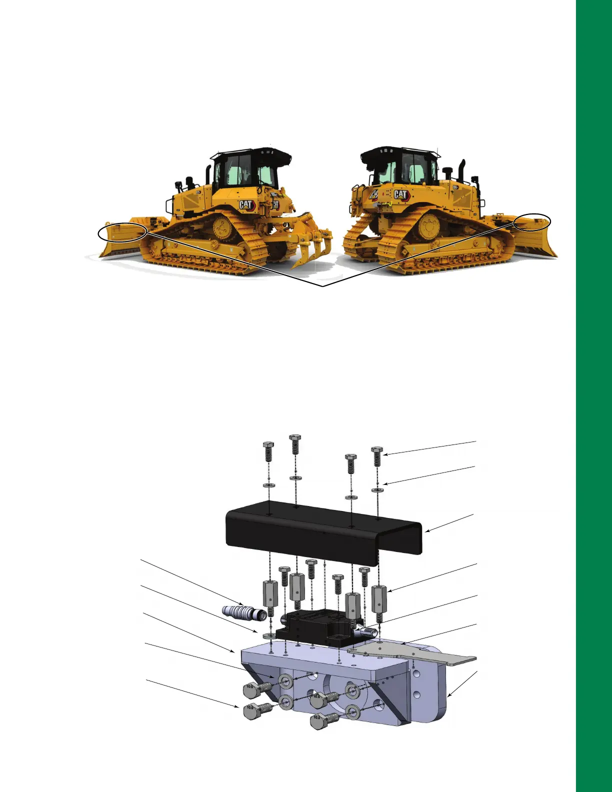
Figure 2-2: TS-i4 Blade Sensor Installation Location
6. Position the 4 Hole Weld-on plate (P/N 9625-1009), provided in TS-i4 Dozer Base Platform
bracket, P/N 1040755-01 (Figure 2-3), on the back of the blade.
7. Use a smart level to ensure the plate is level and parallel to the cutting edge bolts.
8. Use a permanent marker to outline the 4 Hole Weld-on plate location on the blade for welding.
Figure 2-3: TS-i4 Dozer Blade Base Platform Bracket, P/N 1040755-01
TS-i4 IMU sensor can be mounted on either the
left or right side on the back of the blade.
TS-i4 SENSOR
HOSE STRAIN
RELIEF PLATE
M16 x 18 HH
8 PLCS
WASHER,
.31 X .75 X .06
4 PLCS
COVER
STANDOFF, M-F
M6 x 30MM
4 PLCS
TS-i4 IMU SENSOR
4 HOLE WELD-ON PLATE
TS-i4 DOZER BASE
PLATFORM
WASHER, .42X.81X.12
4 PLCS
M10-1.5 X 25 HH
4 PLCS
TERMINATOR
WASHER, FLAT
M6 - THICK STEEL
2 PLCS