12
ASSEMBLY PROCEDURE
ASSEMBLY PROCEDURE
ASSEMBLY PROCEDURE
(1) Selecting Voltage and Fuse
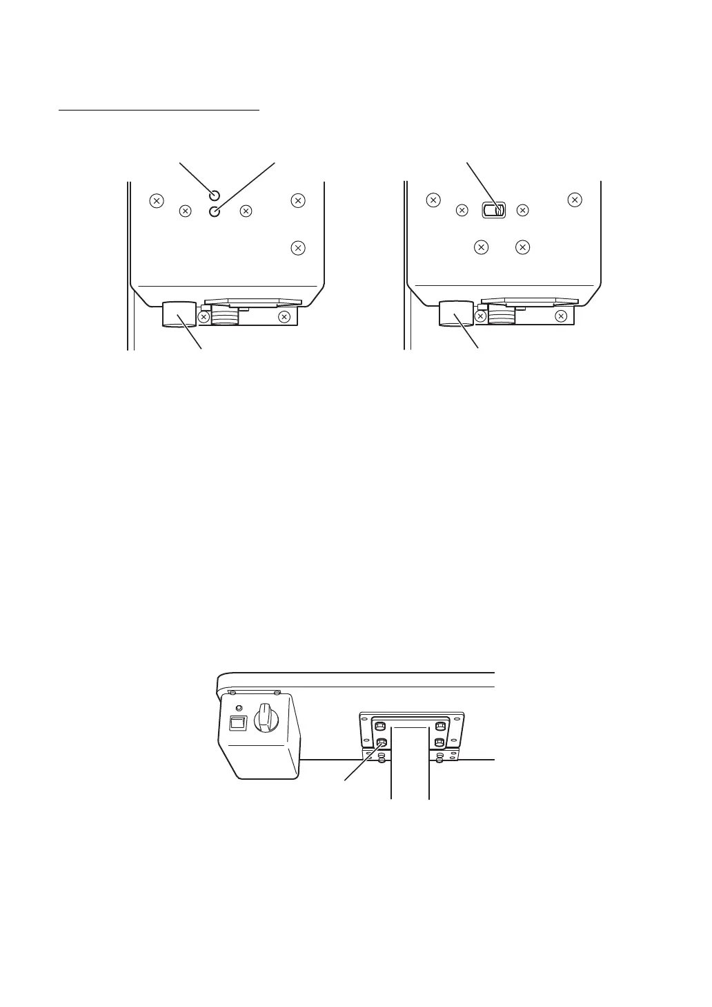
* Check the setting on the voltage selector, which is located on the bottom of the power supply.
* If the selector does not match the outlet voltage, turn the selector to the proper setting with a
screwdriver.
* Turn the center of the fuse holder with the Phillips screwdriver, remove the fuse and check it's
rating. Insure that the fuse is the correct rating for the supplied voltage:
(except for U.S.A. and Canada) (for U.S.A. and Canada)
F1, F2: T1AL 250V(100, 120V) F1, F2: T1AL 250V(120V)
T500mAL 250V(220, 240V) T500mAL 250V(220V)
F3: F4AL 125V F3: F4AL 125V
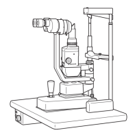
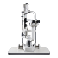
(2) Mounting the Table
(a) To attach the table on the instrument table AIT-15, use the four 8×24mm bolts with locking
washers.
* Raise the table to allow the bolts to pass through the mounting flange.
* Place the table on the mounting flange of the table and screw the bolts into the mounting
bracket. The controls of the power supply should face the practitioner. Tighten the bolts
securely with the included wrench.
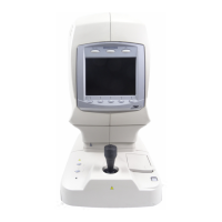
Display window
Voltage selector
Fuse holder
[except for U.S.A. and Canada]
Voltage selector
Fuse holder
[for U.S.A. and Canada]