11
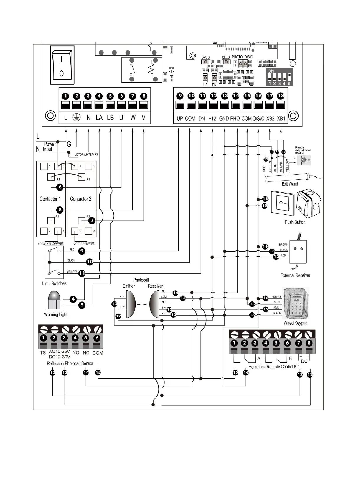
terminal to the “15” terminal.
5. Reflection Photocell Sensor (optional)
The “AC10-25V/DC12-30V” terminals of the reflection photocell sensor should be connected to the “12”
and “13” terminals, no matter the polarity.
The “NC” terminal should be connected to the “14” terminal.
The “COM” terminal should be connected to the “15” terminal.



 To Next Page