10
desired close position when the close limit switch approaches it.
Push the gate fully open by hand. Locate and install the magnet bracket so
that the opener will stop at the desired open position when the open limit
switch approaches it.
The magnet component with S pole must be installed at left side and the
magnet component with N pole must be installed at right side from the
view inside of property.
Ensure magnet center to align with the marked line above !
The magnets should be 25~30mm (1-1.2”) away from the Limit Switch Box.
If it is too near or too far, the switches will fail to work. Adjust the position of the magnets until the positions of
the opening and closing meet the requirement.
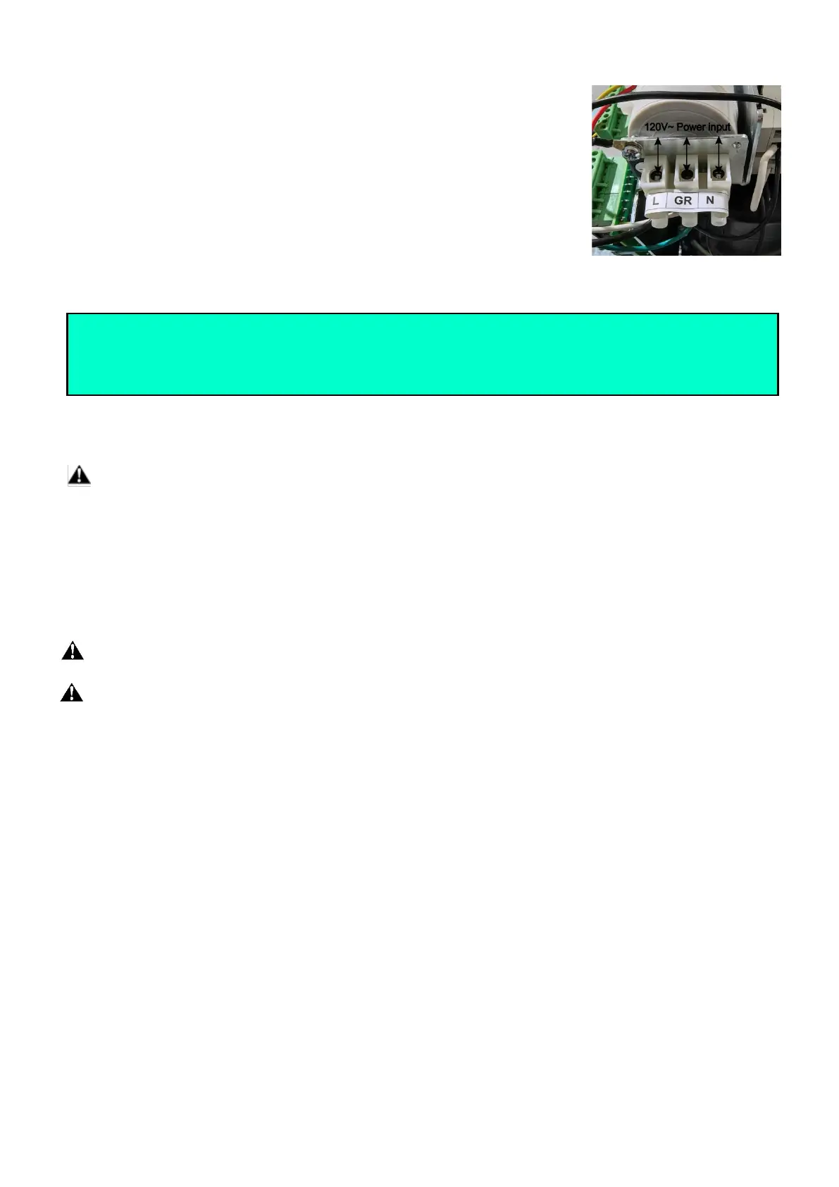
Connecting of Power Supply
WARNING: NEVER connect the gate opener to the power outlet before all the installations have
been done.
The power supply cord should be at least 3×2mm2 (3C×14AWG). Connect the live wire and neutral wire to
the “L” (1#) and “N” (3#) terminal of the power input terminals respectively; and connect the earth wire to
“GR” (2#) terminal of the power input terminals.
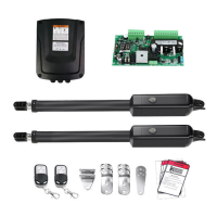
Connecting of the Control Board
Warning:Before making any electrical wire connection or/and setting the control board, make
sure that the power switch is OFF.
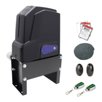
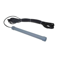
Warning: A photocell sensor is included in the package. The photocell must be installed with the
gate opener for SAFETY PROTECTION. The jumper wire between the PHO & COM terminals (NO.14 &
NO.15) MUST BE REMOVED before installing the photocell.
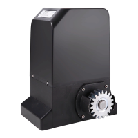
1. Contactors
The A1 terminal of both contactors should be wired to the “6” terminal of the control board.
The A2 terminal of contactor1 should be connected into the “8” terminal the control board.
The A2 terminal of contactor2 should be connected into the “7” terminal the control board.
2. Limit Switches
The RED wire of the limit switches should be connected into the “9” terminal.
The BLACK wire of the limit switches should be connected into the “10” terminal.
The YELLOW wire of the limit switches should be connected into the “11” terminal.
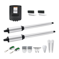
3. Warning Light (Included in some models, refers to the actual package)
One wire of the warning light should be connected into the “4” terminal, another should be connected into
the “5” terminal.
4. Photocell Beam System (PBS) (Normally Closed)
Use a 2-core cable to connect the “+ ~” terminal of the photocell’s emitter to the “12” terminal, the “- ~”
terminal to the “13” terminal. Also the “+ ~” and “- ~” terminals of the photocell’s receiver should be
connected to the “12” and “13” terminals in parallel.
Use another 2-core cable to connect the “NC” terminal of the receiver to the “14” terminal, the “COM”
 Loading...