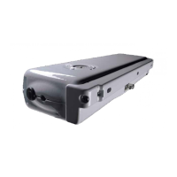
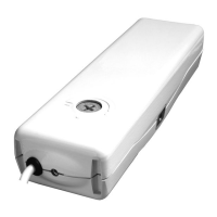
2) CONTROL AND FEEDING UNIT:
controlling the single actuator or
more than one actuator simultaneously by means of one or more manual push-
buttons, an infrared remote control or a 433 Mhz radio control.
To these control units, it is possible to connect rain sensors , wind sensor
and brightness sensor.
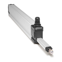
5.7- CORRECT ASSEMBLY OF THE ACTUATOR ON THE WINDOW FRAME
THE CORRECT ADJUSTMENT OF THE WINDOW FRAME CLOSING ASSURES THE LIFE
AND THE TIGHTNESS OF THE SEALS, AS WELL AS THE GOOD OPERATION OF THE
ACTUATOR.
1) With open window frame, verify that the selected stroke is some centimetre lower
than the stroke limited by window frame mechanical limit devices;
Microprocessor control units (e.g.: Mod. TF, etc.)
TO ASSURE A CORRECT OPERATION OF THE ACTUATOR, THE COMMAND AND
FEEDING UNITS EVENTUALLY USED HAVE TO PROVIDE POWER SUPPLY TO THE
ACTUATOR FOR MAX. 120 sec.
BEFORE OPERATING THE ACTUATOR, THE USER MUST COMPULSORILY VERIFY THAT
NEAR AND/OR UNDER THE WINDOW THERE ARE NOT ANY PERSON, ANIMAL AND
THING WHOSE SAFETY MAY BE ACCIDENTALLY JEOPARDISED (SEE PAR. 4.4).
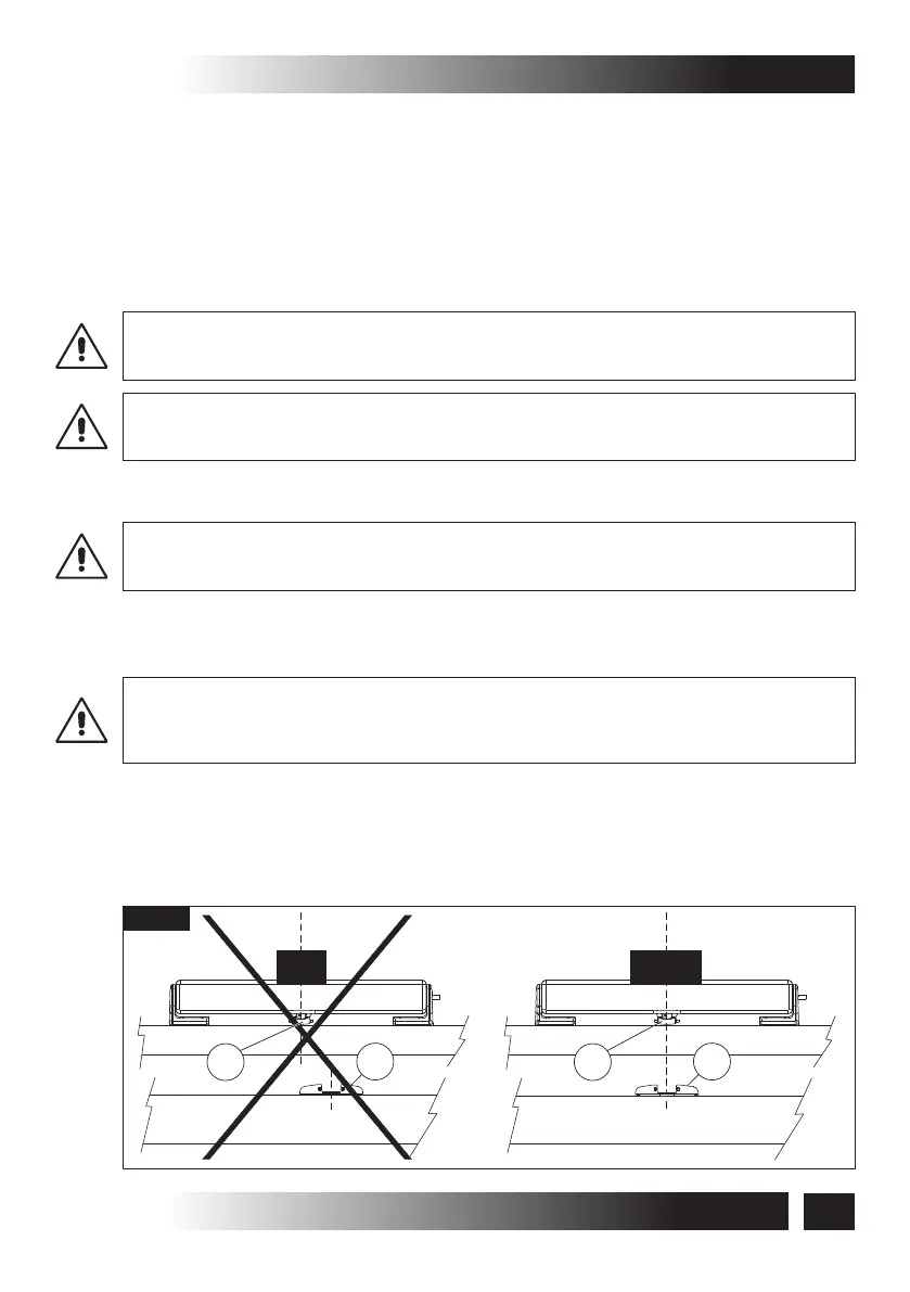
VERIFY THAT THE CHAIN END IS ON THE SAME AXIS OF THE QUICK COUPLING.
OTHERWISE, LOOSEN THE TIGHTENING SCREWS AND POSITION CORRECTLY. WHEN
THE DEVICES ARE NOT COAXIAL, DAMAGES TO THE ACTUATOR AND THE WINDOW
FRAME MAY ARISE (FIG. 11).
2) Verify that the two support brackets of the actuator are aligned to each other and the
four tightening screws are well tightened. Between the two brackets and the actuator
there must not be any clearance.
(RD - 12V)
(RW)
Fig. 11
A
B
B
NO
YES
A
25
C20
VER.0.0
REV.09.13
INSTALLATION AND USE ISTRUCTIONS
INSTALLATION -5