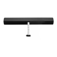
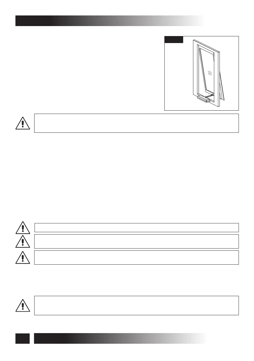
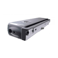
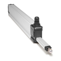
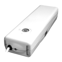
5.2- TOP HUNG WINDOWS
(Fig. 8 and Fig. 19 ÷ 27)
1) Open the package (par. 3.7) and extract the various
components;
2) Fig. 19- With a pencil draw the centre line “X” of the
window frame;
3) Fig. 20- Apply the adhesive template (Ref. 1) on the
window frame aligning it with the previously drawn
centre line “X”;
CAUTION: FOR NON-COPLANAR WINDOW FRAMES, IT IS NECESSARY TO CUT THE
ADHESIVE TEMPLATE CONCERNED PART AND TO APPLY IT ON THE WINDOW FRAME
PAYING ATTENTION TO KEEP IT IN THE SAME REFERENCE POSITION.
4) Fig. 21- With a suitable drill, create on the window frame holes having the related
diameter, given on the adhesive template;
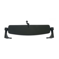
5) Fig. 22÷24- With the suitable screws tighten the brackets for window frame
connection (right - left) and the quick coupling;
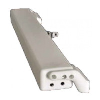
6) Fig. 25/26- After having connected the electric connector in the actuator, perform the
electric connections according to the provisions of par. 5.5, as well as with reference
to the wiring diagram. Let the chain come out for at least 5 cm of stroke, then
disconnect the connector;
7) Fig. 26- Connect the chain end to the quick coupling;
8) Fig. 27- Fasten the actuator to the brackets for connection to the window frame using
the suitable screws;
VERIFY IN Fig. 7a THE CORRECT FASTENING POSITIONING OF THE ACTUATOR.
MAKE SURE THAT THE RED LABEL LOCATED ON THE QUICK COUPLING
CORRESPONDS TO THE SAME LABEL ON THE ACTUATOR.
VERIFY THAT AFTER THE TIGHTENING THE CONNECTION BRACKETS TO THE WINDOW
FRAME ADHERE TO THE ACTUATOR IN ORDER TO ASSURE A CORRECT APPLICATION.
9) Fig. 27- Select the wished stroke (I= 240 mm - II= 360 mm) using the switch (Ref. 1)
located on one side of the actuator. The actuator is supplied with the stroke set on 240
mm.
10) Fig. 25- Insert the electric connector;
TO CHANGE THE PRE-SET STROKE, USE A SCREWDRIVER (FIG. 27) WITH SUITABLE
TIP. MAKE SURE TO INSERT THE TIP UP TO THE MICROSWITCH BASE AND TO SHIFT IT
COMPLETELY. AN INCORRECT IN-BETWEEN POSITION STALLS THE ACTUATOR.
Fig. 8
20
C20
VER.0.0
REV.09.13
INSTALLATION AND USE INSTRUCTIONS
5- INSTALLATION