Thefollowingexampleillustratestheprocessgivenan
installationusingthemachineatan18%pitchonlevel
ground:
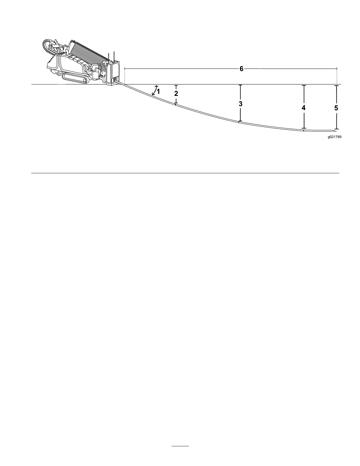
•Youinserttherst3m(10ft)ofdrillbit/pipeintothe
groundwithnosteering.Theendofthedrillbitwillbe
53cm(21inches)deep(Figure29).
Figure29
1.18%pitch3.96cm(38inches)5.119cm(47inches)
2.53cm(21inches)4.114cm(45inches)6.10.6m(35ft)
•Youbeginsteeringupforthenext3m(10ft),pushingthe
pipesinatthemaximumpitchchangeof8%.Thisresults
inachangeofpitchfrom18%atthebeginningofthe3m
(10ft)to10%attheendofthe3m(10ft)foranaverage
pitchof14%.Giventhat,thedrillheadlowersanother43
cm(17inches)andisnow96cm(38inches)deep.
•Continuingsteeringupforthenext3m(10ft)atan8%
pitchchange,yourpitchwillchangefrom10%to2%for
anaveragepitchof6%.Giventhat,thedrillheadlowers
another18cm(7inches)andisnow114cm(45inches)
deep.
•Levelingthedrillheadfrom2%to0%takeslessthan1.5
m(5ft)moreforanaldepthof119cm(47inches).
Reachingthisnalpointtookthreeandahalf,3m(10
ft)pipes.Soforthisexampleyourentrypointshouldbe
10.6m(35ft)backfromthebeginning-at-depthpointof
yourinstallation.
Important:Youcanusetheinformationcontainedin
thissectiontodetermineboththespaceneededtosteer
uptotheexitpointifneededandalsotosteeraround
obstacles.
MappingtheBore
Withtheinformationyougatheredpreviously,mapoutthe
routeofthebore,identifyingthefollowingsothatyoucan
markthesitelater:
•Entrypoint
•Locationofthemachineandsupportingequipment
•Beginningofboreatdepth
•Anyobstaclesthatyouneedtosteeraroundandthe
locationswhereyouneedtostartsteeringtogetaround
orunderthem
•Anyutilitylinesyouwillneedtocross
•Slopeandsoilchangesalongthepaththatwillaffectthe
bore
•Endoftheboreatdepth
•Exitlocationifdifferentthantheendofthebore
38